
By Michael Nielsen, Publisher | 15+ Years in Diesel Repair & Fleet Operations
Last Updated: September 2026
⏱ Estimated reading time: 16 minutes
Diesel engine sensor diagnostics form the foundation of effective troubleshooting for modern commercial vehicles. When a fleet truck pulls into your shop with erratic performance or a warning light lit, the electronic control systems and monitoring devices usually hold the answer — these precision components manage fuel injection timing, air-fuel ratios, turbocharger boost, and emissions compliance, and a failed sensor shows up fast as reduced fuel economy, lost power, excessive smoke, or a check engine light.
This guide walks fleet managers, diesel technicians, and owner-operators through identification, testing, and replacement procedures for the sensors that matter most — the systematic version, not the parts-swap version that leaves the actual wiring or connector problem unresolved, the same standard heavydutyjournal.com applies across its diagnostics coverage.
Key Takeaways
- ✓Sensors control performance immediately. Fuel injection, boost pressure, and emissions all depend on accurate sensor data — failure shows up right away, not eventually.
- ✓Most "sensor" codes aren't actually the sensor. Technicians widely report that a large majority of sensor-related fault codes trace back to wiring, connector corrosion, or ground issues rather than a failed component.
- ✓Systematic testing beats guesswork. Scan tools and multimeters identify the specific failure before you replace anything — a code alone never confirms which component is actually bad.
- ✓Emissions sensors carry compliance weight. A failed NOx or O2 sensor can trigger limp mode or block operation entirely under current EPA and FMCSA requirements.
- ✓Early diagnosis prevents cascading damage. A $50-$150 sensor caught early beats the engine or aftertreatment repair it can turn into if ignored.
In This Guide
- Understanding Diesel Engine Sensors and Electronic Control Systems
- Common Types of Sensors in Modern Diesel Engines
- Recognizing Symptoms of Sensor Failure
- Essential Diagnostic Tools and Safety Procedures
- Reading and Interpreting Diagnostic Trouble Codes
- Testing Air Intake, Pressure, Temperature, and Position Sensors
- Testing Emissions Sensors
- Sensor Replacement Best Practices
- Post-Replacement Verification and Preventive Maintenance
- Frequently Asked Questions
Understanding Diesel Engine Sensors and Electronic Control Systems
Sensors are the communication bridge between a diesel engine's mechanical components and its ECU, continuously gathering data and feeding it to the module that acts as the engine's brain. Onboard diagnostic systems depend entirely on that sensor data — air intake volume, fuel pressure, exhaust composition, coolant temperature, crankshaft position — to make thousands of adjustments every minute, optimizing injection timing, boost pressure, and EGR valve operation in real time.
The shift from purely mechanical fuel injection to today's sensor-driven electronic control is why modern diesels start better in the cold, smoke less, and diagnose faster than their predecessors — all of it running over communication protocols like HDJ's SAE J1939, the heavy-duty standard that lets sensor data move between the engine, transmission, and every other module on the truck.
When sensors fail or drift, the consequences ripple through the whole system — the ECU can trigger limp mode, cut power, or spike fuel consumption — which is exactly why prompt diagnosis matters more than it might seem to at first.
| Parameter Monitored | Sensor Type | Critical Function |
|---|---|---|
| Air intake volume | Mass Airflow Sensor (MAF) | Optimizes fuel-to-air ratio |
| Fuel system pressure | Fuel Pressure Sensor | Ensures proper combustion |
| Exhaust composition | Oxygen/NOx Sensor | Maintains EPA compliance |
| Engine position | Crankshaft Position Sensor | Controls injection timing |
Common Types of Sensors in Modern Diesel Engines
The MAF sensor measures both volume and density of intake air using a heated wire or film element that cools as air passes over it, letting the ECU calculate precise fuel delivery — a failing one shows up as rough idle or hesitation on acceleration.
The MAP sensor tracks intake manifold pressure to determine engine load, which matters even more on turbocharged diesels where boost pressure directly affects fuel delivery calculations; it uses a piezoelectric element generating voltage proportional to pressure rather than the resistive approach a temperature sensor uses.
Oxygen sensors monitor exhaust composition to confirm proper fuel-air mixture, and NOx sensors work alongside SCR systems to track nitrogen oxide reduction — both feed directly into EPA emissions compliance. Exhaust gas temperature sensors use thermistor technology to protect turbochargers and DPFs from thermal damage, alerting the ECU before components reach dangerous heat levels.
Crankshaft and camshaft position sensors — typically magnetic or Hall-effect — provide the timing data the ECU needs to know which cylinder needs fuel injection right now. Without accurate position data, an engine can't run at all, which is why position sensor failures often show up as hard starting or a complete no-start rather than a gradual performance decline.
Recognizing Symptoms of Sensor Failure
Faulty sensors rarely fail silently. Power loss on acceleration — especially merging or climbing — and rough idle from incorrect air-fuel ratios are the most common early signs of a failing MAF or MAP sensor. Crankshaft position sensor failures create timing problems severe enough to cause hard starting or an unexpected stall while driving.
Fuel economy typically drops 10-30% when sensors feed the ECU bad data, and exhaust smoke color narrows the search fast: black smoke points to overfueling from an air intake sensor problem, white smoke to unburned fuel from a temperature sensor issue, and blue smoke to oil consumption possibly tied to a turbo boost sensor malfunction. Michael Nielsen's shortcut for a quick field triage: check smoke color and idle quality first, since both point toward a specific sensor family before you ever plug in a scan tool.
The check engine light means the system has stored a diagnostic trouble code identifying a specific problem; a glow plug light staying on longer than normal, or a DPF regeneration light appearing too frequently, both point toward sensor-driven decisions the ECU is making based on data you should verify rather than ignore. Limp mode is the ECU protecting the engine from a condition it can no longer trust its own sensor data to manage safely.
80%+
Share of sensor-related diagnostic codes that diesel technicians commonly trace to wiring, connector, or ground issues rather than the sensor itself — a widely repeated field observation, not a single formal study.
Essential Diagnostic Tools and Safety Procedures
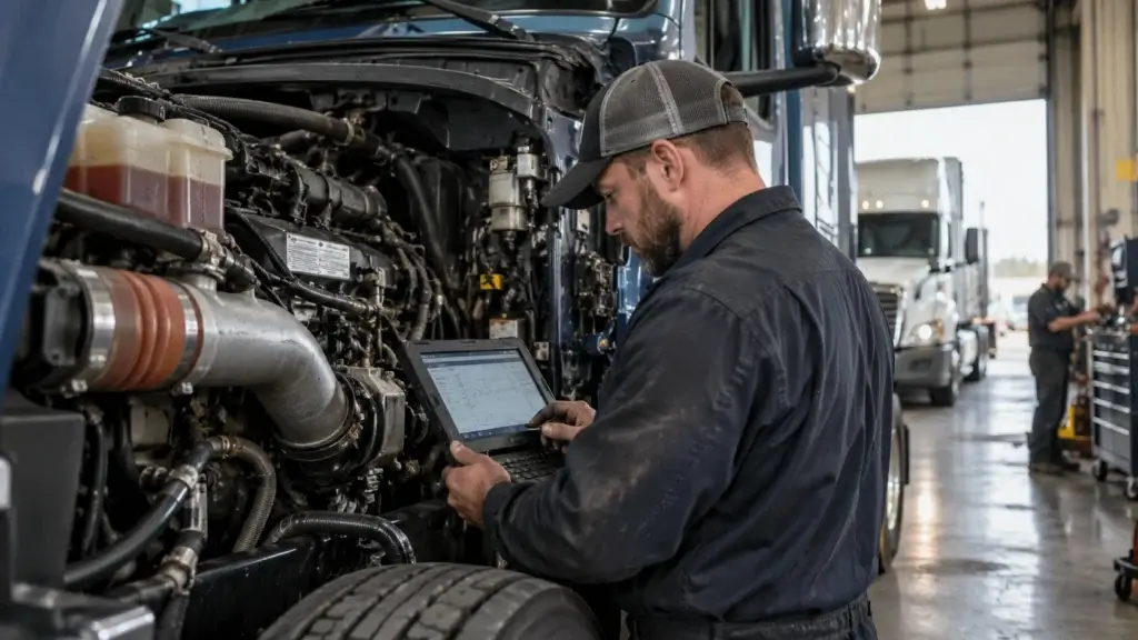
An OBD scanner connects to the vehicle's data link connector to pull diagnostic trouble codes and monitor real-time data — basic code readers handle retrieval and clearing, but professional-grade tools add live data streaming, bi-directional controls for commanding components during testing, freeze-frame capture, sensor graphing, and manufacturer-specific functions for Cummins, Duramax, and Power Stroke platforms. HDJ's evaluation of Noregon JPRO covers what a professional multi-brand platform actually costs and whether it's worth it for your shop.
A digital multimeter checks power supply voltage, ground continuity, signal output, and wire resistance — the four things that answer "is this actually the sensor, or is it the wiring." An oscilloscope goes further for dynamic sensors that produce changing signals: crankshaft and camshaft position sensors and mass airflow sensors all benefit from waveform analysis that a static multimeter reading simply can't show.
HDJ's CAN bus diagnostics guide covers the physical-layer wiring and connector testing techniques behind that 80%+ figure above in much more depth, including the specific resistance and voltage ranges to check.
Basic safety still matters here: disconnect the battery negative terminal before working on electrical systems, wear appropriate PPE, ensure ventilation when running an engine indoors, use jack stands rather than relying on a hydraulic jack alone, and follow lockout-tagout procedures for fleet applications as required under OSHA regulations.
Reading and Interpreting Diagnostic Trouble Codes
Standardized "P" codes indicate powertrain issues, with sensor-related codes typically falling in the P01xx-P03xx range — P0100-P0199 covers fuel and air metering including MAF and MAP, P0101 flags a MAF range problem, P0235 a turbo boost sensor circuit issue, and P0335 a crankshaft position sensor circuit fault. On heavy-duty trucks running J1939, the equivalent information comes through SPN/FMI pairs instead — HDJ's SPN and FMI fault code guide covers that system if your fleet runs Class 8 equipment rather than the lighter platforms where P-codes are standard.
Current codes are active right now; pending codes are intermittent and unconfirmed; permanent codes are confirmed emissions failures needing a specific drive cycle to clear; history codes are previously active faults worth reviewing for a pattern.
None of that changes the core rule: a code alone never confirms the sensor itself is bad. Wiring, connector corrosion, and ECM input problems generate the identical code, and codes can mean different things across engine brands — always cross-reference the manufacturer's specific definition and pair the stored code with live data before condemning a part.
| Code Type | Definition | Diagnostic Action |
|---|---|---|
| Current Codes | Active faults occurring now | Immediate testing required |
| Pending Codes | Intermittent issues detected | Monitor during test drives |
| Permanent Codes | Confirmed emissions failures | Complete repair and drive cycle |
| History Codes | Previously active faults | Review for recurring patterns |
Testing Air Intake, Pressure, Temperature, and Position Sensors
Start MAF testing with a visual check for dirt, oil contamination from an over-oiled air filter, or physical damage to the sensing element — any of the three throws off the reading before you even get to electrical testing. On a scan tool, light-duty diesels typically show 2-7 g/s at idle and 15-25 g/s at 2,000 RPM; readings outside that indicate either sensor failure or an airflow restriction upstream. Electrically, verify the 5-volt reference, check ground continuity, and confirm output voltage in the 0.5-4.5V range depending on airflow.
MAP sensor testing follows a similar reference/ground check, then reads engine-off voltage around 4.5V at sea level (atmospheric pressure), 1-2V at idle, and proportionally higher under boost — a hand vacuum pump lets you simulate pressure changes on the bench and verify the response curve without starting the engine.
The coolant temperature sensor typically reads 2,000-3,000 ohms at 70°F, dropping to 200-300 ohms at 210°F as the engine warms — disconnect it, measure resistance, and compare against the manufacturer's resistance-temperature curve, or pull it and test in a heated water bath for a full-range check.
Fuel pressure sensors on common-rail systems operate at 5,000-30,000+ PSI depending on load; verify with a mechanical gauge at the rail's test port and compare to scan-tool data — cranking should show roughly 5,000-8,000 PSI, idle 6,000-10,000 PSI, and anything more than 500 PSI off between gauge and sensor output means the sensor needs calibration or replacement.
Position sensors split into two testing approaches: magnetic reluctance sensors generate their own AC signal (0.5-10V AC while cranking, 200-900 ohms internal coil resistance, air gap 0.020-0.050 inches), while Hall-effect sensors need external power (5V or 12V) and produce a square-wave digital signal you verify with a scan tool rather than a simple AC voltage check.

Testing Emissions Sensors
Oxygen sensors need their heater circuit checked first, since the element has to reach 600-900°F before it produces a usable signal — a current clamp or voltage-drop test confirms the heater is doing its job before you chase the sensor signal itself.
NOx sensors measure exhaust content on both sides of the SCR catalyst to confirm DEF injection is actually working; a failed one triggers warning lights and can force reduced power. EPA emissions regulations mean a malfunctioning emissions sensor isn't just a performance problem — it can prevent legal operation of the vehicle outright.
Sensor Replacement Best Practices
Gather the right tools before starting — sockets, wrenches, a torque wrench, dielectric grease, thread sealant where required — and inspect all electrical connections for corrosion, looseness, or broken wires before assuming the sensor itself is the problem; a real share of "sensor" issues turn out to be wiring once you actually look.
OEM sensors guarantee exact fit and spec; quality aftermarket sensors from Bosch, Delphi, or Denso perform reliably at lower cost since those manufacturers supply plenty of OEM parts themselves. Avoid cheap no-name sensors — incorrect calibration or poor temperature tolerance shows up as a comeback, not a savings.
Remove exhaust-mounted sensors from a warm engine, not hot or cold, to avoid thread seizure, using a proper oxygen-sensor socket with a wiring cutout where needed. Apply anti-seize to the threads while keeping it well clear of the sensing element, and torque to spec — over-tightening cracks the sensor body, under-tightening risks an exhaust leak. Some replacements need a relearn procedure afterward (throttle position, injector quantity adjustment); skipping that step can leave poor performance or a stored code even though the new sensor itself works fine.
Post-Replacement Verification and Preventive Maintenance
Never clear codes until every repair is complete and connections are secure — use the scan tool's erase function, not a battery disconnect, which wipes adaptive memory, radio presets, and security codes along with the fault history you actually wanted to clear. Cycle the ignition after clearing and check immediately for the code's return, then monitor live data at idle, through throttle changes, and under load: a MAF sensor should climb steadily with throttle input, a coolant sensor should warm gradually rather than jump.
Visual sensor checks belong in every 5,000-10,000 mile or annual service interval. Contamination is the leading cause of premature failure — an over-oiled air filter fouls a MAF sensor, carbon buildup dulls an oxygen sensor's response — so keep filters properly oiled, address oil consumption promptly, apply dielectric grease to connectors, and buy fuel from reputable suppliers.
Fleets subject to 49 CFR Part 396 should document every sensor inspection and repair as part of a systematic maintenance program — that record supports FMCSA compliance and gives you the history to spot a recurring problem before it becomes an expensive one, the same standard heavydutyjournal.com applies across every preventive maintenance topic it covers.
Frequently Asked Questions
What are the most common symptoms of failing diesel engine sensors?
Power loss on acceleration, rough idle, poor fuel economy, colored exhaust smoke, a check engine light, hard starting, or stalling. Many engines enter reduced power mode when a critical sensor fails — see the Recognizing Symptoms section above for what each smoke color and symptom typically points to.
Can a basic OBD-II code reader handle diesel sensor diagnostics?
It'll pull stored codes on engines built after 1996, but it can't stream live data, run bi-directional tests, or access manufacturer-specific functions. Thorough diagnosis needs a professional scan tool — see the Diagnostic Tools section above.
Should I buy OEM or aftermarket sensors?
Quality aftermarket sensors from Bosch, Delphi, or Denso perform comparably to OEM at 30-50% lower cost, since those brands supply many OEM parts anyway. Avoid unknown no-name brands, especially for emissions sensors where failure risks reduced power mode.
How do I tell a bad sensor from a wiring problem?
Check power and ground first, then the output signal against spec. A wiggle test on the harness while watching live data often reproduces an intermittent fault. If the sensor tests correctly off the vehicle but the code returns once reconnected, the wiring or connector is the real problem.
Why does the check engine light come back after I clear the code?
The underlying problem wasn't actually fixed. Common culprits: an overlooked wiring issue, the wrong sensor replaced, a defective new part, a missed calibration step, or an ECM-side problem. Retest thoroughly before replacing yet another sensor on a guess.
Catching diesel sensor problems early is the difference between a quick fix and expensive downtime. Quality diagnostic tools pay for themselves through accuracy and speed, preventive care stops small issues from becoming major repairs, and when replacement is genuinely necessary, systematic testing plus proper installation beats random parts-swapping every time.
Help Fellow Technicians Master Sensor Diagnostics
Share this guide with a fleet manager or diesel technician who could use a more systematic approach to sensor troubleshooting — it beats a shelf full of returned parts.