
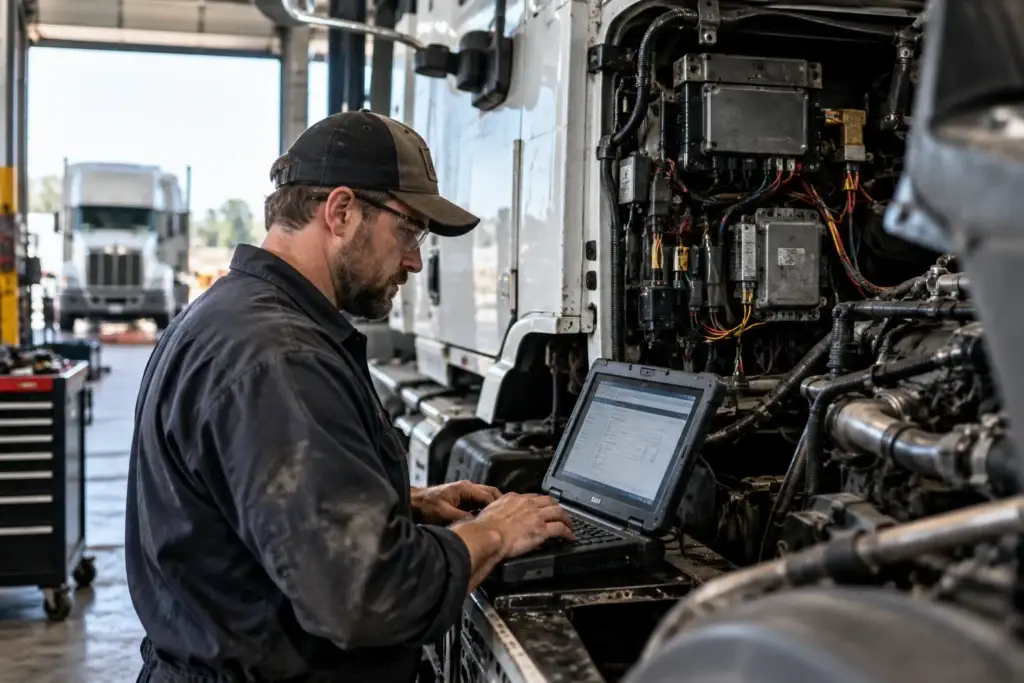
By Michael Nielsen, Publisher | 15+ Years in Diesel Repair
Last Updated: September 2026
⏱ Estimated reading time: 15+ minutes
Modern commercial trucks, buses, and construction equipment rely on a standardized communication language that lets their electronic systems talk to each other. The SAE J1939 standard serves as this universal language, enabling heavy-duty vehicle communication between dozens of electronic control units throughout a vehicle — the translator that lets an engine computer share data with the transmission, brakes, and dashboard.
Heavy Duty Journal's ongoing coverage of heavy-duty diagnostics tracks how this protocol shapes daily troubleshooting — from decoding a single fault code to isolating a failed control module on a mixed fleet. As of September 2026, J1939 remains the dominant standard across virtually every commercial vehicle category on the road.
This communication standard evolved from earlier technologies like J1708 and J1587. The industry needed something faster and more capable as vehicles became more complex. Built on top of the CAN bus physical layer, it quickly became the preferred choice across the entire commercial vehicle sector.
For fleet technicians, understanding this system is no longer optional. Diagnostic excellence depends on knowing how electronic control units exchange critical information like vehicle speed, torque commands, and oil temperature. Mastering these fundamentals separates competent mechanics from expert diagnosticians who can efficiently troubleshoot today's sophisticated machinery.
Key Takeaways
- ✓J1939 is the industry-standard communication language for commercial-vehicle electronics, enabling cross-manufacturer diagnostics with a single compatible scan tool instead of a separate system per brand.
- ✓Built on CAN bus technology, J1939 replaced the older J1708/J1587 protocol with 250 kbaud communication and priority-based message arbitration.
- ✓Understanding SPNs (what failed) and FMIs (how it failed) transforms cryptic fault codes into targeted repair strategies instead of trial-and-error part swapping.
- ✓Proper network termination (approximately 60 ohms total) prevents most communication failures — always test resistance before replacing a module.
In This Guide
- What Is J1939 and Why Fleet Technicians Need It
- Understanding the CAN Bus Foundation
- J1939 Protocol Basics
- J1939 Message Structure and Priority System
- Parameter Group Numbers (PGNs) Explained
- Suspect Parameter Numbers (SPNs) and Failure Mode Indicators
- J1939 Network Architecture in Heavy-Duty Vehicles
- Diagnostic Tools and Software for J1939
- Common J1939 Troubleshooting Scenarios
- Building Your J1939 Expertise
- Frequently Asked Questions
1. What Is J1939 and Why Fleet Technicians Need It
Fleet technicians who master J1939 gain immediate access to comprehensive heavy-duty vehicle diagnostics across multiple equipment types. This standardized protocol eliminates the confusion of proprietary systems and creates a universal language for vehicle electronics. Every modern commercial vehicle relies on this protocol to coordinate its complex electronic operations.
The protocol also reduces wiring complexity significantly. Traditional vehicle designs required separate wire connections between each component. J1939 needs only two wires to connect all electronic modules throughout the entire vehicle network.
Communication Backbone for Vehicle Electronics
J1939 orchestrates interactions between dozens of electronic control modules simultaneously. These modules manage engine performance, transmission shifting, brake systems, emissions controls, and driver information displays. Commercial vehicle communication depends on this protocol to synchronize all electronic vehicle systems in real time.
The protocol handles priority-based messaging that ensures critical safety information always reaches its destination first. Engine shutdown commands and brake warnings take precedence over routine status updates. This intelligent message prioritization protects vehicle operators and equipment.
Equipment Categories Using This Standard
J1939 applications extend far beyond highway trucks. The protocol serves diverse industries and equipment types:
- Long-haul trucks and regional delivery vehicles
- Transit buses and motor coaches
- Construction equipment including excavators and bulldozers
- Agricultural machinery such as combines and tractors
- Military tactical vehicles and support equipment
- Recreational vehicles and specialty conversions
- Marine propulsion systems and navigation equipment
This versatility means technicians can work across multiple sectors rather than specializing in a single vehicle category. The same diagnostic principles apply whether servicing a city bus or a farm tractor.
Practical Advantages for Maintenance Operations
J1939 proficiency delivers measurable improvements in shop efficiency. Technicians complete diagnostics faster through standardized fault codes that identify problems immediately. The protocol enables live data monitoring for intermittent issues that traditional methods miss.
Diagnostic equipment costs decrease through standardization, too. One scan tool works across all J1939-compatible vehicles regardless of manufacturer, eliminating the expense of maintaining separate diagnostic systems for each equipment brand.
$448–$760 per day
Average cost of unscheduled fleet downtime, per ATRI's Operational Costs of Trucking research (as of September 2026)
The protocol also enables predictive maintenance by monitoring system health continuously, so technicians can identify developing problems before they cause breakdowns — reducing downtime and preventing expensive roadside failures.
Communication with technical support teams becomes more effective as well. J1939 provides precise fault descriptions that help manufacturers diagnose complex problems remotely, so technicians spend less time on trial-and-error repairs and more time implementing targeted solutions.
2. Understanding the CAN Bus Foundation
Every J1939 message travels across a physical infrastructure called the CAN bus, a communication system developed specifically for automotive applications. This foundation enables reliable vehicle network communication even in the harsh electrical environments typical of heavy-duty equipment.
The Building Blocks of Vehicle Network Communication
The Controller Area Network was developed by Bosch in the 1980s to solve a growing problem in automotive design. As vehicles added more electronic systems, traditional point-to-point wiring became impossibly complex and heavy.
CAN provides the physical layer and data link layer according to the OSI model framework. The physical layer defines the actual wiring, electrical signaling, and connector standards, while the data link layer handles basic message framing and error detection. This two-layer approach uses twisted-pair wiring with differential signaling, which delivers exceptional noise immunity in electrically harsh environments where alternators, starter motors, and other high-current devices create significant electrical interference.
How Multiple Electronic Control Units Share Information
The genius of CAN lies in its multi-node architecture. Unlike traditional networks requiring a central controller, CAN allows dozens of electronic control units to communicate on a shared two-wire bus simultaneously.
Each ECU can broadcast messages without asking permission. When two ECUs attempt to transmit at the same time, a priority-based arbitration system determines which message proceeds — higher-priority messages always win access to the bus without any data loss or retransmission delays. This ensures critical safety messages reach their destination even during periods of heavy network traffic, and it means diagnostic tools can monitor all bus communication without disrupting normal vehicle operations.
Building J1939 on the CAN Foundation
While CAN bus protocol defines how messages travel across wires, it doesn't specify what those messages mean — this is where J1939 enters the picture as the interpretive framework.
J1939 uses the CAN 2.0B standard with 29-bit extended identifiers rather than the 11-bit identifiers in basic CAN. These additional bits allow the protocol to encode source addresses, destination addresses, priority levels, and parameter group identifiers within each message.
The protocol typically operates at 250 kilobaud, with newer implementations supporting 500 kilobaud for increased bandwidth. J1939 adds network management functions, standardized parameter definitions, and diagnostic protocols on top of the basic CAN infrastructure — CAN handles the reliable message delivery while J1939 provides the standardized language that makes cross-manufacturer communication possible.
3. J1939 Protocol Basics
Understanding J1939 protocol basics starts with recognizing how this standard transformed heavy-duty vehicle communications through structured layers and comprehensive specifications. The standard provides fleet technicians with a unified framework for diagnosing communication issues across different manufacturers and equipment types.
SAE J1939 Standard Overview and Development
The SAE J1939 standard began development in 1985 when the Society of Automotive Engineers recognized the need for standardized heavy-duty vehicle communications. Initial implementation documents emerged in 1994 with the release of J1939-11, J1939-21, and J1939-31, addressing physical connections, data transmission, and network management respectively.
The first comprehensive top-level document appeared in 2000, the same year CAN technology became formally integrated into the J1939 framework. Fleet operators began widespread adoption in 2001 as the standard replaced the older J1708/J1587 protocols. The 2013 Digital Annex release provided electronic access to parameter definitions, streamlining diagnostic software development.
Recent enhancements include J1939-17 and J1939-22, released between 2020 and 2021, which enable J1939 communication over CAN FD for higher-bandwidth applications. SAE International maintains the standard as a living document with regular revisions to address emerging technological needs.
Protocol Layers and Network Architecture
The J1939 protocol layers organize vehicle communications into six distinct specifications within the SAE J1939 Standards Collection. Each layer addresses specific technical requirements that work together to enable reliable data exchange.
- J1939/11 (Physical Layer) defines the electrical specifications including 250 kbaud transmission speed and twisted shielded pair wiring requirements
- J1939/21 (Data Link Layer) covers message framing, transport protocol functions, and how data packets move across the network
- J1939/31 (Network Layer) handles address claiming procedures that allow ECUs to identify themselves on the bus
- J1939/71 (Vehicle Application Layer) contains thousands of standardized parameters covering engine performance, transmission status, and vehicle operations
- J1939/73 (Application Layer — Diagnostics) specifically addresses diagnostic messages, fault codes, and trouble reporting mechanisms
- J1939/81 (Network Management) defines functions for controlling network behavior and managing communication priorities
This layered architecture separates concerns so technicians can isolate problems to specific system levels — physical wiring issues present differently than application-layer parameter errors, making systematic diagnosis more straightforward.
Key Differences from J1708, OBD-II, and CAN 2.0
Fleet technicians transitioning from light-duty automotive work or older heavy-duty systems need to understand critical distinctions between communication protocols. The older J1708 protocol operated at 9,600 baud using RS485 electrical signaling, making it significantly slower than J1939's 250 kbaud CAN-based communication. Sequential message transmission in J1708 created potential bottlenecks, while J1939's priority-based arbitration ensures critical messages gain immediate bus access.
| Protocol Feature | J1708/J1587 | OBD-II | J1939 |
|---|---|---|---|
| Communication Speed | 9,600 baud RS485 | Variable (250–500 kbaud) | 250 kbaud CAN |
| Message Priority | Sequential transmission | Limited priority support | Priority-based arbitration |
| Parameter Standardization | Basic PIDs | Emissions-focused PIDs | Comprehensive 8,000+ parameters |
| Diagnostic Coverage | Engine and drivetrain | Emissions systems primary | All vehicle systems |
OBD-II protocols vary by manufacturer and concentrate primarily on emissions-related diagnostics for regulatory compliance. J1939 provides comprehensive coverage across all vehicle systems including braking, suspension, and body control functions. Raw CAN 2.0 offers only basic message structure without standardized parameter definitions, while J1939 includes extensive parameter specifications that enable cross-manufacturer compatibility — which is exactly why it became the dominant standard for commercial vehicles.
4. J1939 Message Structure and Priority System
The architecture of J1939 messages relies on a carefully engineered 29-bit identifier system that packs critical routing information into a compact digital format. Understanding this structure lets fleet technicians decode network traffic, troubleshoot communication problems, and interpret diagnostic data with greater accuracy.
Every message transmitted across a J1939 network uses the CAN 2.0B extended frame format. This architecture divides the 29-bit CAN identifier into three distinct fields that work together to route and prioritize data throughout the vehicle's electronic systems.
Understanding the 29-Bit Identifier
The 29-bit identifier serves as the message's complete addressing and priority system. Rather than functioning as a simple destination address, it contains layered information that tells receiving modules what the message contains, where it came from, and how urgently it needs processing.
| Field Name | Bit Length | Position | Function |
|---|---|---|---|
| Priority | 3 bits | Bits 26–28 | Determines message urgency (0–7 scale) |
| Parameter Group Number | 18 bits | Bits 8–25 | Identifies message content type |
| Source Address | 8 bits | Bits 0–7 | Identifies sending ECU (0–253) |
Priority Field
The 3-bit priority field establishes message urgency on a scale from 0 to 7, where zero represents the highest priority. Critical safety systems like engine protection shutdown commands or brake requests typically use priority levels 0–2 and always gain bus access before routine data transmissions. Lower-priority messages such as fuel economy calculations use levels 5–7 and may see slight delays during heavy network traffic — all handled automatically, with no technician intervention required.
Parameter Group Number Field
The 18-bit Parameter Group Number identifies what type of information the message contains — think of the PGN as the message's subject line, telling receiving modules whether the data represents engine speed, transmission gear position, brake pressure, or one of thousands of other defined parameters. Diagnostic tools decode the PGN into human-readable parameter names, so a technician sees "Engine Speed" rather than the raw PGN value 61444.
Source Address Field
The 8-bit source address identifies which electronic control unit transmitted the message, supporting up to 254 unique modules on a single network. When diagnosing communication faults, the source address helps trace messages back to a specific component — a fault reported from source address 0, for example, typically points a technician to the engine control module.
Message Arbitration and Bus Access
J1939 networks use bus arbitration to determine which message transmits when multiple ECUs attempt to communicate simultaneously. This relies on CAN's non-destructive bitwise arbitration, which automatically prioritizes messages without data loss or retransmission delays.
When two modules start transmitting at the same moment, the arbitration mechanism compares their 29-bit CAN identifiers bit by bit. The message with the lower numerical identifier value — which corresponds to higher priority — wins bus access and continues transmitting, while the losing message automatically waits and retries once the higher-priority message completes.
This resolves in the same transmission cycle, at the hardware level, which is exactly why J1939 networks never need a master controller or a separate traffic-management scheme: the priority built into each message's identifier creates a self-organizing system that adapts to varying network loads on its own.
Data Field Organization and Byte Order
J1939 messages carry up to 8 bytes of actual data following the identifier. The protocol organizes this data field using Intel byte order (little-endian format), where multi-byte values transmit least significant byte first — a 16-bit engine speed value of 1500 RPM (0x05DC) would appear on the network as 0xDC followed by 0x05.
Most diagnostic software handles this byte swapping automatically. Understanding Intel byte order still matters when troubleshooting data interpretation errors or validating a custom diagnostic script against actual network traffic.
5. Parameter Group Numbers (PGNs) Explained
Parameter Group Numbers transform complex CAN bus messages into actionable diagnostic information. These standardized identifiers create a universal framework that lets technicians work across multiple equipment brands with consistent diagnostic procedures — a single scan tool interprets data from Caterpillar, Cummins, Detroit Diesel, and other brands because they all use the same PGN structure.
PGN Structure Breakdown
The J1939 PGN comprises an 18-bit subset of the 29-bit extended CAN identifier. This 18-bit field divides into four distinct components that determine message routing and interpretation.
| PGN Component | Bit Length | Function | Typical Values |
|---|---|---|---|
| Reserved Bit | 1 bit | Future expansion | Always 0 |
| Data Page | 1 bit | Page selector | 0 or 1 |
| PDU Format | 8 bits | Message type identifier | 0–255 |
| PDU Specific | 8 bits | Group extension or destination | 0–255 |
Multiple CAN messages with unique identifiers can map to the same PGN and be interpreted identically. The Data Page bit effectively doubles the available PGN space by creating two separate pages of message definitions.
PDU Format and PDU Specific Fields
When PDU Format is 240 or greater, the message is classified as PDU2 type, and the PDU Specific field contains a Group Extension that further defines the parameter content. When PDU Format is below 240, the message is PDU1 type, and the PDU Specific field instead contains a Destination Address for point-to-point communication between specific control modules.
Broadcast vs. Peer-to-Peer Messages
Approximately 95% of J1939 messages are broadcast messages (PDU2 type), transmitted to all network nodes simultaneously — most operational parameters like engine speed and vehicle speed work this way. Peer-to-peer communication (PDU1 type) targets specific control modules for diagnostic requests, acknowledgments, and command messages, with the Destination Address field ensuring only the intended recipient processes the message.
Essential PGNs Every Fleet Technician Should Know
- PGN 61444 — Electronic Engine Controller 1: engine speed and torque data, transmitted at high frequency
- PGN 65265 — Cruise Control/Vehicle Speed: wheel-based vehicle speed from transmission or ABS modules
- PGN 65262 — Engine Temperature 1: coolant temperature and oil temperature for thermal management
- PGN 65263 — Engine Fluid Level/Pressure 1: oil pressure, fuel pressure, and related critical parameters
- PGN 65226 — Active Diagnostic Trouble Codes: currently active fault codes broadcast for immediate attention
The J1939 Digital Annex contains comprehensive technical details for all standard PGNs. PGNs from 00FF00 through 00FFFF are reserved for proprietary use by manufacturers for specialized equipment functions.
How to Decode PGN Data in Real Time
Diagnostic software uses J1939 Digital Annex specifications or DBC files to translate raw hexadecimal data into meaningful physical values automatically. Understanding the manual process still helps technicians verify diagnostic tool accuracy and troubleshoot communication issues.
The decoding process follows four steps: identify the PGN from the CAN identifier, extract the relevant data bytes per the PGN specification, apply the specified byte order to arrange multi-byte values correctly, then use the scaling factor and offset to convert raw values into engineering units like RPM, PSI, or degrees Fahrenheit.
6. Suspect Parameter Numbers (SPNs) and Failure Mode Indicators
Every fault code a diagnostic tool displays contains two critical pieces of information: the Suspect Parameter Number identifying which component failed, and the Failure Mode Identifier explaining how it failed. Together, these elements form the foundation of J1939 fault codes that guide repair decisions.
The J1939 Digital Annex contains over 10,000 standardized SPNs covering every measurable vehicle parameter, each pointing to a specific signal that exceeded normal limits or stopped functioning entirely. For a deeper walkthrough of pulling these codes in the field, see HDJ's guide to finding SPN and FMI fault codes.
Understanding SPNs in Vehicle Diagnostics
Suspect Parameter Numbers serve as unique identifiers for individual data elements within Parameter Group Numbers. Each SPN represents a specific measurable parameter — engine coolant temperature, turbocharger boost pressure, throttle position sensor voltage — helping technicians pinpoint exactly which component triggered a diagnostic trouble code.
Every SPN contains precise technical attributes that define how to extract and interpret its data: bit start position, bit length, and scale/offset values that convert raw binary data into meaningful physical measurements. Common examples include SPN 190 for Engine Speed, SPN 84 for Wheel-Based Vehicle Speed, and SPN 96 for Fuel Level. Special signal values add diagnostic context — a data byte of 0xFF (255) means the parameter data is not available, while 0xFE (254) signals an error condition in data transmission.
Failure Mode Identifier (FMI) Codes Explained
While SPN codes identify which parameter failed, FMI codes specify how that parameter failed — a companion value that completes the diagnostic picture. The J1939 standard defines 32 standardized FMI values ranging from 0 to 31, each corresponding to a specific failure mode.
Common FMI Values and Their Meanings
| FMI Code | Failure Description | Typical Cause | Diagnostic Focus |
|---|---|---|---|
| FMI 0 | Data valid but above normal range | Sensor reading too high | Check for actual high condition or faulty sensor |
| FMI 1 | Data valid but below normal range | Sensor reading too low | Verify actual low condition or sensor failure |
| FMI 2 | Data erratic or intermittent | Unstable sensor signal | Inspect wiring, connectors, and sensor integrity |
| FMI 3 | Voltage above normal or shorted high | Circuit shorted to power | Check for wiring damage or sensor short |
| FMI 4 | Voltage below normal or shorted low | Circuit shorted to ground | Look for grounded wires or connector issues |
Additional critical FMI values include FMI 5 for current below normal or open circuit conditions, FMI 6 for current above normal or grounded circuits, and FMI 7 for mechanical systems not responding properly. FMI 31 serves as a general indicator that a condition exists without specifying the exact failure mode.
Occurrence Count and Active vs. Inactive Faults
J1939 diagnostic messages track fault history through occurrence counts that record how many times a specific fault appeared since the last code clearing, revealing whether a problem is a one-time event or a recurring issue. Status indicators distinguish currently active faults, which demand immediate attention, from inactive historical faults that cleared themselves or were repaired.
Occurrence counts above one on an inactive fault suggest an intermittent problem that may return — a useful early signal for vibration-related connector failures, temperature-dependent sensor issues, or load-sensitive electrical problems that disappear under certain operating conditions.
Translating SPN-FMI Combinations into Actionable Repairs
Converting abstract codes into concrete repair strategies requires systematic methodology. When a scan tool displays SPN 94 FMI 1, look up the SPN first — 94 corresponds to fuel delivery pressure — then interpret the FMI: 1 indicates data valid but below normal operating range. Together, these point toward low fuel pressure conditions, typically from restricted fuel filters, a failing transfer pump, or air intrusion in the fuel system.
SPN 110 FMI 3 works the same way: engine coolant temperature with voltage above normal or shorted high, pointing to either a shorted coolant temperature sensor or damaged wiring between the sensor and ECU. Identify the parameter through the SPN, understand the failure mode through the FMI, then apply technical knowledge of that system to narrow probable causes — this structured methodology transforms fault codes from confusing numbers into precise repair roadmaps.
7. J1939 Network Architecture in Heavy-Duty Vehicles
The J1939 network architecture creates a communication backbone that connects every major system in heavy-duty vehicles. Modern trucks and buses contain dozens of specialized electronic control units that continuously exchange operational data through carefully designed vehicle wiring and communication protocols.
Electronic Control Units (ECUs) on the J1939 Network
Electronic control units represent the intelligent nodes that make modern vehicles possible. Each ECU manages specific systems while sharing critical information across the network. The number of ECUs varies by vehicle specification and model year — a basic truck might have eight to twelve modules, while advanced specifications can contain more than twenty separate controllers.
Engine Control Module (ECM)
The ECM serves as the powertrain's central controller. It manages fuel injection timing and quantity for optimal performance and emissions compliance, controls turbocharger boost levels, and coordinates aftertreatment regeneration. It continuously broadcasts engine speed and torque output, coolant and oil temperature, fuel system pressure, and emissions system status — other modules depend on this data for proper operation, and the ECM also enforces engine protection limits to prevent damage during abnormal operating conditions. HDJ's ECM diagnostics guide covers systematic troubleshooting for this module in depth.
Transmission Control Module (TCM)
The TCM manages all aspects of transmission operation through constant communication with the engine controller. It determines optimal shift points based on load, speed, and driver demand, and controls torque converter lockup and torque reduction during gear changes — coordination that prevents harsh shifts and drivetrain damage. In return, the TCM receives driver throttle input and reports current gear selection, output shaft speed, and transmission temperature.
Antilock Braking System (ABS) and Other Controllers
The ABS module monitors wheel speeds and controls brake modulation during emergency stops; modern stability control systems build on this foundation to prevent rollovers and loss of control. Additional specialized modules keep expanding in newer vehicles — instrument clusters, body controllers for lighting and accessories, advanced driver-assistance systems, and telematics gateways that connect vehicles to fleet management platforms.
Physical Network Topology and Wiring Standards
J1939 networks use a linear bus topology where all modules connect to a common backbone. The SAE J1939/11 physical layer standard specifies twisted shielded pair wiring operating at 250 kilobaud, with newer implementations supporting 500 kilobaud for increased data capacity.
Each ECU connects through short stub connections to the main network backbone. Stub length matters significantly for signal integrity — long stubs create signal reflections that corrupt data transmission and cause communication errors. The twisted-pair design reduces electromagnetic interference from engine components and electrical systems, with shielding providing additional protection in harsh vehicle environments.
⚠️ Safety Warning
Never disconnect or reconnect J1939 network connectors with the ignition on. Hot-plugging can damage ECU drivers and corrupt network communication, potentially causing safety system failures. Michael Nielsen and HDJ's editorial team recommend always turning the ignition off before performing any network wiring repair.
Termination Resistors and Network Resistance Testing
Termination resistors play a critical role in J1939 network operation. The network backbone must have 120-ohm resistors installed at both ends to prevent signal reflections that would otherwise bounce back through the network.
Technicians verify proper termination through simple resistance testing: disconnect all modules from the network, then measure resistance between CAN High and CAN Low terminals. A properly terminated network reads approximately 60 ohms with both terminators present. Missing resistors lead to intermittent communication failures; extra terminators reduce overall resistance and weaken signals; wrong-value resistors create similar issues that manifest as communication errors or complete network failure.

8. Diagnostic Tools and Software for J1939
Modern heavy-duty diagnostics demand both capable hardware interfaces and intelligent software to translate J1939 data into actionable insights. Fleet technicians face numerous choices when investing in J1939 diagnostic tools, from manufacturer-specific platforms to versatile aftermarket solutions.
Effective diagnostics require hardware that physically connects to the vehicle's J1939 network through the standardized diagnostic connector. The J1939-13 standard specifies a 9-pin Deutsch connector, using pin C for CAN high and pin D for CAN low signals; some vehicles feature secondary J1939 networks accessible through pins F/G or H/J for specialized systems.
Connector types matter for shop compatibility. Type 1 connectors work only with matching Type 1 sockets, limiting flexibility; Type 2 green connectors, introduced in 2013–14, offer backwards compatibility with Type 1 sockets alongside enhanced durability — worth checking before selecting a diagnostic adapter for a shop servicing diverse equipment ages.
OEM Diagnostic Software Platforms
Engine and vehicle manufacturers provide proprietary diagnostic applications offering the deepest access to their specific products — parameter programming, calibration updates, and advanced testing procedures unavailable through generic tools. Investment in a manufacturer-specific platform makes sense for fleets concentrated on one engine brand, where the enhanced capability justifies the higher cost.
Cummins INSITE
Cummins INSITE stands as the industry-leading platform for diagnosing Cummins engines. It provides fault code reading with detailed troubleshooting guidance, extensive live data monitoring through customizable gauge displays, cylinder cutout testing to isolate individual cylinder performance, and datalog recording that captures intermittent problems during road testing. Its parameter programming and ECM calibration capabilities let technicians configure engine operating parameters and install the latest software directly.
Detroit Diesel Diagnostic Link (DDDL)
Detroit's DDDL delivers comparable functionality specifically for Detroit engines, with particular strength in diagnosing integrated powertrain systems that combine engine, transmission, and emissions controls. The platform supports software updates, parameter configuration, and specialized testing, including detailed regeneration monitoring and component testing for Detroit's aftertreatment systems.
Caterpillar Electronic Technician (Cat ET)
Cat ET is the required diagnostic tool for Caterpillar engines and machines across construction, mining, and on-highway applications — fault diagnostics with manufacturer-specific trouble codes, performance monitoring of engine and hydraulic data, and configuration capability for adjusting machine settings, software updates, and calibrations.
Aftermarket Scan Tools and J1939 Adapters
Aftermarket solutions provide multi-manufacturer coverage for shops servicing diverse equipment brands at lower cost than maintaining multiple OEM platforms. Handheld scan tools deliver code reading, live data viewing, and basic diagnostics across multiple engine brands through a single device, while PC-based systems combine J1939 adapters with software for extensive data logging and network analysis — useful for capturing bus traffic, identifying misbehaving nodes, and verifying message timing.
The versatility of aftermarket tools supports efficient workflows in mixed-fleet operations, letting technicians perform initial diagnostics across all equipment types before deploying OEM tools for brand-specific programming or calibration work.
Selecting the Right Diagnostic Equipment for Your Shop
Shops supporting a single engine brand benefit from investing in OEM tools despite the higher initial cost — the comprehensive functionality and manufacturer support justify the expense. Multi-brand fleet operations need a different strategy: aftermarket equipment providing cross-platform coverage becomes essential for cost-effective daily diagnostics, and many successful shops maintain both OEM tools for deep diagnostic work and aftermarket tools for routine fault reading across brands.
Software subscription costs, update frequency, and laptop compatibility requirements all factor into the decision, along with training and support responsiveness. The Commercial Vehicle Safety Alliance maintains inspection standards that require accurate diagnostic capability for compliance verification.
| Platform Type | Best Application | Key Advantages | Typical Investment |
|---|---|---|---|
| Cummins INSITE | Fleets with Cummins engines | Complete programming access, advanced testing | $1,500–$2,500 plus annual subscription (industry estimate, as of September 2026) |
| Detroit DDDL | Detroit-powered equipment | Integrated powertrain diagnostics, calibration | $1,200–$2,000 plus annual subscription (industry estimate, as of September 2026) |
| Caterpillar ET | Cat engines and machines | Machine system integration, configuration | $1,800–$3,000 plus subscription (industry estimate, as of September 2026) |
| Aftermarket Handheld | Multi-brand basic diagnostics | Cross-platform coverage, portability | $300–$1,500 one-time cost (industry estimate, as of September 2026) |
| PC-Based Aftermarket | Advanced multi-brand diagnostics | Data logging, network analysis | $500–$2,000 plus optional updates (industry estimate, as of September 2026) |
The most effective diagnostic equipment strategy balances capability with cost: identify the most common diagnostic scenarios and equipment brands a shop actually sees, invest in tools that address those needs first, then add specialized capabilities over time as requirements expand.
9. Common J1939 Troubleshooting Scenarios for Fleet Technicians
J1939 troubleshooting typically involves three main problem categories: complete network failures with no communication, partial failures affecting specific modules, and intermittent issues that appear unpredictably. Combining diagnostic software analysis with physical network testing resolves most of these systematically.
Diagnosing Communication Errors and Bus-Off Conditions
A bus-off condition is a protective state where a CAN controller stops transmitting after detecting excessive communication errors — typically because it transmitted data but received no acknowledgment, due to a disconnection, improper termination, or being the only active node.
Start by verifying connector engagement at the diagnostic port and checking for power and ground, then measure network resistance to confirm proper termination — approximately 60 ohms indicates correct dual termination, and this test must be performed with all modules disconnected for an accurate reading. Diagnostic software adds insight here too: rising error counts indicate deteriorating network health even before complete failure occurs. For a deeper walkthrough of this exact process, see HDJ's CAN bus troubleshooting guide for heavy-duty trucks.
Identifying Failed or Misbehaving ECUs
Isolating a problematic module means distinguishing between a completely failed unit and one transmitting corrupted data. Monitoring which ECUs respond to diagnostic requests reveals communication capability — request messages using PGN 59904 can poll specific data from ECUs for this purpose, and a module with an abnormally high error counter often signals a hardware problem or software glitch.
Systematically disconnecting modules while monitoring network function identifies disruptive units directly: if network operation improves when a specific module is removed, that module becomes the prime suspect for further testing or replacement.
Resolving Intermittent Network Faults
Intermittent faults present a particularly challenging diagnostic scenario because problems appear only under specific conditions — vehicle vibration, temperature extremes, and moisture exposure frequently trigger them. Wiggle-testing connectors and harnesses while monitoring live communication often reproduces the problem, and dataloggers capture network traffic during failures a technician can't observe in real time.
Checking for corrosion in Deutsch connector pins is critical in harsh operating environments, along with inspecting wiring for chafing at movement points and harness tie-down locations. Aftermarket equipment installations sometimes introduce improper termination or excessive stub lengths that create intermittent communication disruptions of their own.
Troubleshooting Wiring, Connectors, and Termination Issues
Physical network problems represent the most common source of J1939 troubleshooting calls. An added terminating resistor from a prior repair produces too-low network resistance; a corroded or damaged connector pin creates an intermittent connection that appears and disappears with vehicle operation.
| Physical Issue | Symptom | Diagnostic Method | Expected Result |
|---|---|---|---|
| Missing Termination | Intermittent communication errors | Measure network resistance | 120 ohms (should be 60 ohms) |
| Extra Termination | Weak signals, communication failures | Resistance check with modules disconnected | 30–40 ohms (should be 60 ohms) |
| Corroded Connector Pins | Intermittent module communication loss | Wiggle test while monitoring live data | Communication drops during movement |
| CAN High/Low Short | Complete network failure | Continuity test between wires | Zero resistance between CAN_H and CAN_L |
Incorrect wire gauge or untwisted pairs compromise signal integrity in a similar way, and excessive stub lengths from modules to the backbone create reflections that corrupt data transmission.
Systematic Diagnostic Approach for J1939 Problems
A logical troubleshooting workflow prevents wasted time: gather symptom information (when problems occur, what functions are affected), use diagnostic software to identify which modules aren't communicating, measure network resistance to verify termination, then inspect physical connections at the diagnostic port and suspect modules for obvious damage or corrosion.
The TMC Recommended Practices library provides standardized diagnostic procedures for this kind of systematic troubleshooting. Monitor live network traffic to identify communication patterns and errors, isolate sections of the network or individual modules to narrow the problem, and verify the repair by confirming normal network resistance, successful communication with all modules, and clearing of previously stored network-related fault codes. HDJ's guide to reading diesel DTC codes covers the code-level side of this same workflow.
10. Building Your J1939 Expertise
J1939 mastery transforms capable technicians into diagnostic experts. This protocol follows a "keep it simple" philosophy while handling complex vehicle communication across multiple electronic control units — its multi-master architecture gives every ECU equal network access without hierarchical limitations.
Fleet technician skill in heavy-duty diagnostics correlates directly with protocol understanding. Technicians who interpret PGNs and SPNs confidently reduce diagnostic time and solve problems that confuse others relying only on guided procedures — expertise that works across equipment brands rather than locking a technician into a single manufacturer.
Professional development in J1939 requires hands-on application beyond reading a guide: practice decoding parameter groups during routine maintenance calls, and experiment with diagnostic software features to build familiarity with different manufacturer implementations. Network communication patterns often reveal intermittent faults that a simple code reader misses entirely.
The protocol continues evolving with CAN FD implementations, but its core principles remain constant. Michael Nielsen and Heavy Duty Journal's editorial team have tracked this protocol's evolution for years, and the investment in understanding 29-bit identifiers, message arbitration, and parameter structures provides lasting career value as heavy-duty diagnostics grow more sophisticated each year.
Certification programs from ASE and manufacturer training programs expand these capabilities further. Treat protocol proficiency as an ongoing journey rather than a finished destination — technicians who commit to continuous learning gain a real competitive advantage in diagnostic speed, repair quality, and career growth across the commercial vehicle industry. For more diagnostic deep-dives like this one, check back at heavydutyjournal.com.
Frequently Asked Questions
What is J1939 and what does it do?
J1939 is the standardized communication protocol used by electronic control units in heavy-duty vehicles. Built on CAN bus technology, it enables real-time data exchange between engine controllers, transmissions, and brake systems, using standardized PGNs and SPNs so any compatible scan tool can diagnose any manufacturer's equipment.
How is J1939 different from OBD-II?
J1939 was built for commercial vehicles; OBD-II targets passenger cars. J1939 runs at 250 kbaud with over 8,000 standardized parameters covering every vehicle system, while OBD-II focuses mainly on emissions diagnostics — see the protocol comparison table above for the full breakdown.
What diagnostic tools work with J1939?
OEM platforms — Cummins INSITE, Detroit DDDL, Caterpillar ET — give brand-specific programming and calibration access. Aftermarket scan tools and PC-based J1939 adapters cover multiple brands at lower cost. See the platform comparison table above for typical investment ranges.
What causes J1939 communication failures?
Missing or damaged termination resistors, corroded connector pins, wiring damage from chafing or vibration, and failed ECUs are the most common causes. Improper repairs that add extra termination or excessive stub length can also trigger intermittent faults — see the physical-issue table above.
What do SPN and FMI codes mean?
The SPN identifies which parameter triggered a fault — like coolant temperature (SPN 110) or fuel pressure (SPN 94). The FMI explains how it failed, from 0 (above normal range) to 31 (condition exists). SPN 110 FMI 3, for example, points to a shorted coolant temperature sensor circuit.
How do I test J1939 network termination?
Disconnect all modules and measure resistance between CAN High and CAN Low at the diagnostic connector. A properly terminated network reads approximately 60 ohms; 120 ohms means a missing terminator, and below 60 ohms means extra termination was added during a prior repair.
Share This J1939 Guide
Know a technician leveling up their diagnostic skills? Pass this along, or bookmark heavydutyjournal.com for the next protocol deep-dive.