
By Michael Nielsen, Publisher | 15+ Years in Diesel Repair & Fleet Operations
Last Updated: September 2026
⏱ Estimated reading time: 16 minutes
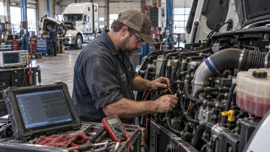
Diesel engine sensor diagnostics separate skilled technicians from parts replacers — and the sensor-by-sensor detail is where that separation actually happens. This guide works through eight of the most common failure points one at a time, with the specific voltage, resistance, and pressure values (and, for the sensors where it matters, the oscilloscope waveform) that confirm a component is actually bad before you replace it.
For the broader picture — sensor categories, DTC code interpretation, and replacement best practices — HDJ's diesel engine sensor testing and replacement guide covers that ground. This piece stays focused on the specific test values for eight sensors technicians see fail most often.
Key Takeaways
- ✓Systematic testing prevents costly errors. Structured procedures identify the actual failed sensor rather than replacing parts based on symptoms that several sensors share.
- ✓Contamination causes most failures. Regular maintenance of air filters, fuel filters, and cooling systems extends sensor life more than any other single habit.
- ✓Scan tool data needs verification. Compare electronic readings against a mechanical gauge or oscilloscope pattern before condemning a sensor — the two don't always agree.
- ✓Temperature-dependent failures are common. Several sensors test fine cold and fail only at operating temperature — dynamic testing catches what a static check misses.
- ✓OEM sensors earn their price. Calibrated components matched to ECM programming outlast budget alternatives enough to change the real cost comparison.
In This Guide
- Diesel Engine Sensor Diagnostics: Mass Air Flow Sensor Failure
- Crankshaft Position Sensor Malfunction
- Fuel Rail Pressure Sensor Diagnostics
- Exhaust Gas Temperature Sensor Breakdown
- DPF Pressure Sensor Problems and Solutions
- Turbocharger Boost Pressure Sensor Issues
- Camshaft Position Sensor Failure
- Engine Coolant Temperature Sensor Malfunctions
- Preventing Diesel Sensor Failures Through Maintenance
- Frequently Asked Questions
Diesel Engine Sensor Diagnostics: Mass Air Flow Sensor Failure
The MAF sensor feeds the ECM real-time intake air volume data, and when it drifts, fuel delivery calculations go with it — rough idle, black smoke under acceleration, a real fuel economy hit, and hesitation that gets worse on cold starts and at altitude. Contamination is the primary cause: oil residue from an over-oiled aftermarket air filter, or plain dirt from a clogged one, coats the sensitive hot-wire or hot-film element and distorts the reading.
Start with a visual check — pull the sensor and inspect the element under good light for oil residue, dirt, wire damage, or moisture inside the housing. Light contamination often responds to a cleaner made specifically for MAF sensors (never carb or brake cleaner, which damage the element); apply in short bursts from about six inches away and let it fully evaporate before reinstalling.
Electrically, confirm 12-14V on the power supply wire with ignition on, then watch scan tool data through idle, a snap-throttle test, and under load — a healthy sensor shows a smooth, progressive climb in airflow readings as RPM rises, with no flat spots or erratic jumps.
Crankshaft Position Sensor Malfunction
An engine that cranks but won't fire puts this sensor first on the suspect list — it tracks exact crankshaft position and speed, and without that data the ECM has no basis for injection timing. Intermittent stalling at operating temperature is the other classic sign, since internal components can break down under heat and lose signal temporarily before recovering as things cool.
Visually check the mounting for damage, loose bolts, or oil contamination, and trace the harness for wear near hot exhaust components or sharp edges. The air gap between sensor tip and reluctor wheel typically runs 0.020-0.050 inches — too much kills the magnetic field, too little risks contact damage. Resistance should read 500-1,500 ohms at room temperature; zero means a short, infinite means an open circuit.
For the cases resistance testing doesn't resolve, an oscilloscope is the real diagnostic tool: a healthy sensor produces a consistent AC waveform with uniform amplitude across every reluctor tooth, one distinct spike per tooth in a repeating pattern tied to rotation. Inconsistent amplitude between peaks means weakening magnetic strength; missing or distorted peaks mean damaged reluctor teeth or sensor degradation; and amplitude that gradually drops as the engine warms up confirms the heat-related failure that resistance testing alone would miss entirely.
Fuel Rail Pressure Sensor Diagnostics
Common rail diesels depend on this sensor for precise pressure data — typically 5,000-30,000 PSI depending on load — and when it's wrong, injection timing and quantity go wrong with it. Hard starting, especially in cold weather, and sudden power loss under acceleration are the two most common symptoms, since the ECM can't regulate what it can't measure accurately.
| Operating Condition | Expected Pressure Range | Diagnostic Indicator |
|---|---|---|
| Cold Idle | 5,000-7,000 PSI | Stable readings within 200 PSI |
| Warm Idle | 6,000-8,000 PSI | Consistent without fluctuation |
| Light Acceleration | 12,000-18,000 PSI | Smooth pressure increase |
| Full Throttle/Load | 20,000-30,000 PSI | Peak pressure sustained |
A mechanical gauge on the fuel rail's test port gives the definitive answer, run alongside scan tool data at the same time to isolate the sensor as a variable. If the mechanical gauge reads 15,000 PSI while the scan tool shows 10,000, the sensor is clearly wrong and needs replacement. If both readings match but sit below spec, the problem is elsewhere in the fuel system — a worn pump, a clogged filter, a restricted line — not the sensor at all.
Exhaust Gas Temperature Sensor Breakdown
EGT sensors monitor heat that regularly exceeds 1,200°F, positioned before and after the turbo and at both ends of the DPF, protecting the turbo and managing regeneration timing tied directly to EPA emission standards for particulate control. A failed EGT sensor shows up as incomplete regeneration cycles (the ECM can't accurately judge when to start or finish one), rising soot accumulation, and sometimes limp mode as the engine protects itself from unmonitored heat it can no longer verify is safe.
Pull live data from every EGT sensor simultaneously across varying loads — a pattern single-sensor testing misses. Pre-turbo readings should run 200-400°F higher than post-turbo under load, and DPF inlet should read higher than outlet during normal operation; deviations from that predictable relationship point at a specific sensor rather than the system broadly.
An infrared thermometer at accessible test points confirms actual temperature against the sensor reading — a gap over 50°F means drift or calibration failure. HDJ's DEF system diagnostics guide covers the SCR and DEF-quality side of aftertreatment sensor troubleshooting in more depth if the EGT reading turns out to be correct and the problem is actually downstream.
DPF Pressure Sensor Problems and Solutions
This sensor measures differential pressure across the particulate filter to judge soot loading and trigger regeneration — and when it's wrong, the symptoms look exactly like a genuinely clogged filter even when the filter itself is fine. Frequent regeneration requests right after a completed regen, incomplete cycles, limp mode capping speed around 40-50 mph, and a real fuel economy hit from unnecessary regen cycles are all signs pointing at the sensor rather than the filter.
Before replacing the sensor, check the small-diameter sensing hoses connecting it to the exhaust — carbon buildup blocks pressure transmission, a disconnected or cracked hose lets ambient air in and produces a false low reading, and cold-weather moisture in the lines can freeze and block transmission temporarily. Cleaning or replacing these inexpensive hoses resolves a real share of "DPF sensor" complaints without touching the actual sensor at all.
Turbocharger Boost Pressure Sensor Issues
Boost sensor problems are genuinely tricky because a perfectly good sensor reports incorrect pressure if the intake system leaks — the sensor is accurate, the actual pressure just isn't what it should be. Significant power loss under acceleration or load, and black smoke from over-fueling relative to available air, are the typical symptoms either way.
Smoke testing is the most reliable way to separate a leak from a sensor problem — a professional smoke machine pressurizes the intake, and any leak shows up immediately at intercooler boots and clamps, intake manifold gaskets, turbo outlet connections, or wastegate actuator seals.
Once leaks are ruled out, test the sensor itself: most operate 0.5-4.5V, tracking boost pressure linearly and smoothly through the full range from idle to full boost. Flat-lining during boost events, erratic jumps, or a delayed/stepped response to rapid throttle changes all point to a failing sensor rather than an intake leak. Michael Nielsen's rule for this one: chase leaks before sensors, since a sensor swap on a leaking intake just gets you a new sensor reporting the same wrong number.
Camshaft Position Sensor Failure
Working alongside the crankshaft sensor, this one tells the ECM which cylinder is on its compression stroke and feeds variable valve timing adjustments. Rough or erratic idle that fluctuates randomly, hot-start difficulty (fine cold, longer cranking once warmed up), and intermittent stalling on deceleration are the tell-tale symptoms.
Oscilloscope testing is the gold standard here too: set the scope for 50-500 Hz depending on engine speed, crank the engine, and watch the pattern. Hall-effect sensors produce a clean square wave switching between 0.5V and 4.5V; magnetic sensors produce a sine wave growing in amplitude and frequency with speed. A signal dropout on either type means intermittent failure causing the starting and stalling symptoms.
The ECM constantly checks cam/crank correlation and stores a code when the two disagree beyond tolerance — monitor that correlation value in real time via scan tool, displayed as a degree deviation from expected position. A stretched timing chain or worn gear can shift the camshaft relative to the crankshaft enough to create a real timing error the sensors are correctly reporting, so always verify mechanical timing before condemning a sensor that's technically telling the truth.
Engine Coolant Temperature Sensor Malfunctions
The ECM leans on accurate coolant temperature data for fuel injection timing, glow plug activation, cooling fan control, and emissions management — even minor drift here causes real drivability problems. Hard cold-weather starting (no proper fuel enrichment without accurate cold data), rough idle until warm, and excessive black smoke on warm-up from over-enrichment based on a false cold reading are the classic symptoms.
| Temperature | Resistance (Ohms) | Typical Condition |
|---|---|---|
| 32°F (0°C) | 5,000-6,000 | Cold ambient temperature |
| 68°F (20°C) | 2,300-2,700 | Moderate ambient |
| 176°F (80°C) | 270-330 | Engine partially warmed |
| 212°F (100°C) | 175-210 | Normal operating temp |
Test by removing the sensor, submerging the tip in water alongside an accurate thermometer, and recording resistance at each temperature point above. Infinite resistance means an open circuit, near-zero means an internal short, and erratic readings during heating mean thermistor degradation — all requiring replacement.
Live data monitoring catches what a static test misses too: cold-start reading should match ambient, temperature should climb roughly 3-5°F per minute during warm-up, and reach 180-210°F depending on thermostat rating. If the scan tool shows temperature rising too slowly or never reaching normal range, check for a stuck-open thermostat before blaming the sensor.
Free Diesel Maintenance Checklist
Get HDJ's free, field-tested diesel maintenance checklist delivered instantly to your inbox — print it, laminate it, keep it in the shop.
Instant PDF • 100% Free • No Spam

Preventing Diesel Sensor Failures Through Maintenance
Most sensor problems trace back to contamination, neglect, or environmental exposure rather than a defective component — which means most are preventable. Fuel system cleanliness is foundational: replace filters every 10,000-15,000 miles, buy quality diesel from reputable sources, and use fuel additives that prevent algae growth in contaminated tanks.
Oil changes matter just as much for sensor health — crankcase ventilation vapor gradually coats MAF sensors and intake components with residue, so 5,000-7,500 mile intervals for severe service, using oil meeting the specified API and viscosity ratings, protects more than just the engine internals, the same maintenance discipline heavydutyjournal.com recommends across every sensor-adjacent system it covers.
OEM or OEM-equivalent sensors from Bosch, Delphi, or Denso hold calibration matched to ECM programming — generic aftermarket parts may physically fit but deliver readings outside the tolerance the ECM expects. The ASE L2 Electronic Diesel Engine Diagnosis Specialist certification tests exactly this kind of sensor-level judgment call.
Run the real cost comparison, not just sticker price: a $150 premium sensor lasting 100,000 miles beats three $50 sensors failing every 30,000, once you count the labor for repeated installs, the diagnostic time on recurring problems, and the towing risk from a roadside failure. HDJ's predictive maintenance ROI guide covers that full cost math for fleets weighing the same tradeoff across a whole vehicle population rather than one truck at a time — the same rigor heavydutyjournal.com applies to every ROI claim it publishes.
Frequently Asked Questions
What are the most common signs of a failed diesel sensor?
Check engine light, rough idle, hard starting, black smoke, power loss, poor fuel economy, intermittent stalling, or limp mode. Multiple sensors share these symptoms, which is exactly why systematic testing — not guessing — is what identifies the specific failed component.
Can I keep driving with a failed sensor?
Some failures allow limp-mode operation, but continuing to drive risks real damage — a failed EGT sensor can destroy a turbocharger, and a bad fuel rail sensor can damage injectors or cause catastrophic engine failure. Diagnose and repair promptly.
How do I know if my MAF sensor needs cleaning versus replacement?
Light contamination usually responds to proper MAF cleaner. If cleaning doesn't restore normal readings, voltage falls outside spec, or the element shows physical damage, replace it. See the MAF Sensor section above for the full test procedure.
Why does my truck keep requesting DPF regeneration right after completing one?
Usually a failed DPF pressure sensor or a clogged sensing hose, not an actually loaded filter. Check the small-diameter pressure lines for blockage or cracks before replacing the sensor — see the DPF Pressure Sensor section above.
Should I buy OEM sensors or are aftermarket ones just as good?
OEM or OEM-equivalent (Bosch, Delphi, Denso) is the safer bet — ECMs are calibrated for specific sensor characteristics, and off-spec aftermarket parts can feed inaccurate data even when they physically fit. See the Preventing Failures section above for the real cost comparison.
Systematic diesel sensor diagnostics separates actual failures from symptoms that just mimic them — and catching a real problem early, at the sensor-specific voltage or waveform level, prevents it from cascading into something far more expensive. The procedures here work best paired with HDJ's broader sensor testing and replacement guide for the category-level fundamentals and DTC interpretation this piece assumes.
Help Fellow Technicians Master Sensor Diagnostics
Share this guide with a technician still parts-swapping instead of testing — the specific values here turn a guess into a confirmed diagnosis.