
By Michael Nielsen, Editor & Publisher | 15+ Years in Diesel Repair & Drivetrain Diagnostics
Last Updated: June 2026
⏱ Estimated reading time: 18 minutes
Turbocharger failure diagnosis in heavy-duty diesel engines starts with understanding that more than 90% of turbo failures are caused by one of three preventable root causes: oil starvation, oil contamination, or foreign object damage — not manufacturing defects. Before condemning the turbocharger itself, a systematic diagnosis must rule out upstream causes including restricted oil feed lines, degraded oil quality, boost leaks, faulty sensors, clogged DPF filters, and EGR problems that mimic turbo failure symptoms. This guide walks diesel technicians and fleet managers through the complete diagnosis sequence: reading the symptoms, inspecting the hardware, interpreting fault codes, identifying the true root cause, and making the rebuild-versus-replace decision — so you don't spend $3,000 on a new turbo only to destroy it in the same way as the last one.
Key Takeaways
- 90%+ of turbo failures are oil-related — oil starvation and oil contamination account for the overwhelming majority of heavy-duty turbocharger failures; manufacturing defects cause less than 1%
- Never replace without finding the root cause — industry data shows that when a replacement turbo fails prematurely, 99% exhibit the exact same damage mode as the original, confirming the underlying issue was never addressed
- Blue/white smoke and boost codes don't automatically mean turbo failure — boost leaks, faulty MAP sensors, stuck EGR valves, and clogged DPF filters all generate identical symptoms; proper diagnosis is mandatory before replacement
- Shaft play tolerance is tight — radial movement exceeding 0.010 inches (0.25mm) in heavy-duty applications signals bearing wear requiring immediate action
- VGT turbos carry a complexity penalty — variable geometry turbocharger failures on engines like the Cummins ISX, Volvo D13, and Detroit DD15 require electronic actuator calibration after replacement, not just a parts swap
- 30-second idle before shutdown — the single most common preventable cause of premature turbo failure in fleet operations is hot shutdown without cooldown; it takes 30 seconds to save a $3,000 component
How Turbochargers Fail: The Three Root Causes
A turbocharger is a fundamentally simple machine — an air pump driven by exhaust gas energy that forces compressed air into the combustion chamber, enabling the engine to burn more fuel and produce more power from a given displacement. In heavy-duty Class 6–8 applications, turbocharger shaft speeds routinely reach 100,000 to 200,000 RPM. At those speeds, the shaft and bearing assembly depend entirely on a thin, pressurized film of engine oil for both lubrication and cooling. The margin for error is essentially zero.
Understanding this dependency clarifies why the vast majority of failures are oil-related. According to Garrett Motion, a major turbocharger manufacturer, less than 1% of turbocharger failures are attributable to manufacturing defects. The remaining failures trace to three root causes that fleet operations can control.
Root Cause 1: Oil Starvation
Oil starvation is the leading killer of diesel turbochargers. Running a turbocharger without adequate oil pressure for as little as five seconds causes bearing damage equivalent to running a diesel engine without oil for five minutes. The turbine shaft micro-welds to its housing — a condition that produces shaft seizure, often snapping or separating the shaft entirely and driving compressor or turbine wheel fragments into the engine or intake tract.
Common causes of oil starvation in fleet applications include:
- Kinked, collapsed, or carbon-coked oil feed lines — particularly common on high-mileage engines where sludge deposits gradually restrict the turbo feed passage
- Hot shutdown without cooldown — when a loaded truck shuts down immediately after hard operation, residual heat in the turbo housing bakes the oil in the feed line into carbon deposits (coking); these deposits restrict future oil flow
- Extended oil change intervals that allow oil viscosity to degrade past the point of adequate film strength at operating temperatures
- Worn oil pumps or low oil level reducing system pressure below turbo bearing requirements
- Failure to pre-lube a replacement turbocharger during installation — dry startup after replacement is one of the most common shop errors
Root Cause 2: Oil Contamination
Oil contamination occurs when foreign particles — carbon deposits, fuel dilution, coolant intrusion, metal shavings from upstream wear, or debris from a damaged oil filter bypass valve — enter the turbocharger bearing system. Even microscopic contamination acts as an effective abrasive at turbo speeds, gradually scoring the journal bearing landing areas and thrust surfaces. The damage mode produces characteristic score marks visible on the bearing diameter of the shaft, distinguishing contamination from starvation (which typically shows heat bluing and micro-welding).
When a turbocharger fails due to oil contamination, the entire oil system must be flushed before the replacement unit is installed. Fitting a new turbocharger without flushing contaminated oil from the supply lines and sump virtually guarantees premature failure of the replacement unit through the exact same damage mode. This is the primary reason industry data shows 99% of prematurely failed replacement turbos exhibit identical damage patterns to the original — the root cause was never corrected.
Root Cause 3: Foreign Object Damage
Foreign object damage (FOD) occurs when debris enters either the compressor inlet or the turbine housing. On the compressor side, the source is typically a failed or improperly sealed air filter, a collapsed intake boot, or damaged intake piping that allows unfiltered air to reach the compressor wheel. Even fine airborne particles — the kind that pass a visually clean filter — can erode compressor wheel blade tips at operating speeds. On the turbine side, FOD most commonly originates from upstream engine damage: broken valve seats, piston ring fragments, or debris from an EGR cooler failure entering the exhaust stream.
FOD is often identifiable by characteristic blade tip damage — nicks, erosion patterns, or bent blades visible when the compressor cover is removed. Turbine-side FOD damage is typically more severe and may require engine inspection before turbo replacement to identify and correct the debris source.
90%+
of heavy-duty turbocharger failures are caused by oil starvation or oil contamination — not manufacturing defects. Source: Garrett Motion turbocharger failure analysis
Turbocharger Failure Symptoms: What to Look For Before You Pull It
Experienced technicians know that a turbocharger problem announces itself well before catastrophic failure. The key is recognizing which symptoms indicate a genuine turbo issue versus which indicate an upstream or downstream problem that mimics turbo failure. Mis-diagnosis at this stage is the most expensive mistake in turbo service — replacing a functional turbocharger because of a boost leak or a faulty sensor wastes $3,000 and leaves the real problem in place.
Exhaust Smoke Color Diagnosis
Exhaust smoke color is one of the fastest initial diagnostic indicators for turbocharger problems, but the interpretation requires context:
| Smoke Color | Turbo Indication | Also Check |
|---|---|---|
| Blue smoke (sustained) | Compressor or turbine seal failure — oil entering intake or exhaust | Piston rings, valve seals |
| Blue smoke on decel only | Strong indicator of compressor-side seal failure specifically | Intake tract for oil film |
| Black smoke on acceleration | Possible underboost — engine overfueling due to insufficient boost pressure | Boost leaks, air filter, DPF backpressure, VGT vanes |
| White smoke (persistent) | Coolant-to-turbo leak if sweet smell present | Head gasket, EGR cooler, intercooler |
| Thick black smoke at idle | Less likely turbo — more likely injector or fueling issue | Injectors, EGR valve stuck open |
Power Loss and Boost Lag
A failing turbocharger typically reduces power output by 30–50% as boost pressure drops. Drivers report the truck feeling "flat" during acceleration, struggling on grades it previously climbed easily, or exhibiting pronounced turbo lag that wasn't present before. However, before attributing power loss to the turbocharger, technicians should verify:
- Boost pressure leaks in the charge air system — a hairline crack in an intercooler boot that only opens under boost pressure can produce all the symptoms of a failing turbo with zero actual turbo damage
- Air filter restriction — a plugged air filter starves the compressor of airflow, producing surge, noise, and lag that feels like turbo failure; maximum allowable intake restriction is typically 15–25 inches of water column at rated RPM
- Clogged DPF generating excessive exhaust backpressure — backpressure above 40 inches of water at the turbo outlet overheats the turbine and reduces output; check DPF delta pressure readings before condemning the turbo
Noise: What Sounds Like Turbo Failure
Turbocharger noise falls into recognizable categories. A high-pitched whine or whistle that changes pitch with engine speed typically indicates bearing wear — the noise is the shaft beginning to contact housing surfaces as bearing clearances increase. A sudden loud screeching that doesn't go away signals bearing seizure in progress; immediate shutdown is required. A compressor surge sound — a repeating flutter or chuff during acceleration — indicates the compressor is operating at the edge of its map, often caused by a restriction or boost leak rather than turbo damage itself. Rattling from the turbo area at startup or shutdown often indicates shaft end-play from thrust bearing wear.
Importantly, whistling or whining that correlates with boost codes in the ECM does not automatically confirm the turbo is the fault. Boost codes can be triggered by leaking boost pipes, faulty MAP sensors, stuck VGT actuators, or EGR valve problems — any of which will generate noise and fault codes while the turbocharger itself remains mechanically sound.
Keep Your Fleet Running at Full Capacity
Get HDJ's maintenance guides, compliance updates, and fleet management strategies delivered weekly — built for working diesel professionals.
Oil Consumption and Seal Failure
Increased oil consumption is frequently the earliest detectable sign of turbocharger seal deterioration, often appearing four to eight weeks before visible exhaust smoke or power loss symptoms emerge. Normal diesel engine oil consumption runs approximately 0.1–0.3% of fuel volume; a failing turbo can push consumption to 1–2% or higher. For fleet applications, oil consumption exceeding one quart per 1,000 highway miles warrants immediate investigation of the turbocharger seals.
A quick field check: pull the intake tube off the compressor inlet and inspect the interior of the compressor housing. A light oil mist is normal — this is crankcase ventilation residue. A heavy oil film coating the compressor housing walls points directly at a failed compressor-side shaft seal. On the exhaust side, oil present inside the turbine outlet and downpipe indicates turbine-side seal failure, often accompanied by blue smoke on deceleration.
Step-by-Step Turbocharger Failure Diagnosis Procedure
Systematic turbocharger failure diagnosis follows a sequence that moves from the simplest checks to the most involved — ruling out upstream and downstream causes before physically inspecting the turbocharger itself. This sequence prevents the common mistake of pulling and condemning a turbo that is not at fault.
Step 1: Pull and Interpret Fault Codes
Connect a heavy-duty diagnostic scanner and retrieve all active and stored fault codes. Turbocharger-related codes typically appear as underboost (actual boost below commanded boost), overboost, or VGT position sensor faults. However, interpret these codes as a starting point — not a verdict. An underboost code (such as Cummins SPN 102 FMI 1, or Detroit Diesel SPN 102 FMI 18) tells you the system cannot achieve target boost; it does not tell you whether the turbo, a boost leak, or a downstream restriction is the cause.
Use the scanner's live data function to compare commanded boost to actual boost under load. A large gap between commanded and actual at normal RPM with a mechanically sound boost system points toward the turbocharger; a gap that closes when boost lines are re-pressurized during a leak test points toward the charge air system.
Step 2: Inspect the Charge Air System for Boost Leaks
Boost leaks are the most frequently misdiagnosed cause of apparent turbo failure. A leak anywhere between the turbo compressor outlet and the intake manifold will produce underboost codes, power loss, black smoke, and poor fuel economy — the exact same symptom profile as a worn turbocharger. Pressure-test the entire charge air system before any turbo decision. This involves pressurizing the intercooler and charge pipes with shop air (typically 20–30 PSI) and listening for leaks, or using soap solution on every connection, clamp, and intercooler end tank.
Pay particular attention to intercooler boots and flexible couplers, which harden and crack with heat cycling. Hairline cracks that are invisible during a visual inspection open up under boost pressure — this is why the pressure test is mandatory, not optional.
⚠️ Safety Warning
When performing boost leak tests on hot engines, keep hands clear of charge air connections under pressure. Intercooler boots can blow off at 30 PSI with enough force to cause injury. Wear eye protection when using soap solution near pressurized fittings. Allow the charge air system to cool before disconnecting components for inspection.
Step 3: Check Air Filter Restriction and Intake Condition
A clogged air filter is a remarkably common and easily missed cause of what appears to be turbocharger failure. When the air filter restriction indicator shows restriction in the yellow or red zone — or when a vacuum gauge connected between the filter and compressor inlet shows more than 25 inches of water column at rated RPM — the compressor is working against a significant restriction. This restriction causes compressor surge (the fluttering, chuffing noise often mistaken for bearing noise), reduces boost output, and accelerates compressor wheel and bearing wear over time.
While the filter is out, inspect the entire intake path from the air cleaner housing to the compressor inlet for cracks, collapsed hoses, or debris ingestion. Any evidence of dust contamination past the filter — fine dirt on the compressor wheel or inside the compressor housing — confirms FOD as a contributing failure mode and requires complete system cleaning before installing a replacement turbo.
Step 4: Check Exhaust Backpressure and DPF Condition
Excessive exhaust backpressure from a clogged DPF is a significant and underappreciated cause of turbocharger damage in modern emissions-compliant diesel engines. Backpressure acts on the turbine side of the turbocharger — high backpressure overloads the turbine wheel, drives up exhaust gas temperatures, and accelerates turbine-side seal degradation. Measure exhaust backpressure at the turbo outlet or exhaust manifold using a high-temperature pressure gauge. Most heavy-duty diesel applications should see less than 40 inches of water column at rated power; readings above this threshold indicate DPF restriction that must be addressed before any turbo service.
Confirm DPF condition by checking delta pressure readings across the filter using scanner data. Per 49 CFR § 396.3, motor carriers are required to systematically inspect and maintain all parts and accessories affecting safe operation, which includes aftertreatment systems that impact engine performance and emissions compliance.
Step 5: Physical Turbocharger Inspection — Shaft Play and Wheel Condition
Once upstream and downstream causes have been ruled out, the physical inspection of the turbocharger itself follows a specific sequence:
Radial shaft play (journal bearing check): Grasp the compressor wheel (not the blade tips — grab the center hub) and attempt to move the shaft radially, perpendicular to its axis of rotation. On most heavy-duty turbochargers, acceptable radial play ranges from 0.003–0.010 inches (0.076–0.254 mm) depending on the specific design. Movement at the high end of this range or beyond indicates journal bearing wear. Compare the measured play against the OEM specification for the specific turbocharger model — Cummins, Detroit Diesel, and PACCAR each publish specification tolerances for their respective turbo applications.
Axial shaft play (thrust bearing check): Push and pull the compressor wheel along the axis of rotation. Minimal movement (typically 0.001–0.003 inches) is normal and necessary for thermal expansion. Excessive axial play — the shaft moving noticeably in and out under finger pressure — indicates thrust bearing wear, which commonly produces oil leakage from the compressor side during deceleration.
Wheel condition: With the compressor cover removed, inspect the compressor wheel blades for nicks, erosion, or bent tips that indicate FOD. Check for contact marks on the compressor housing — scoring from wheel-to-housing contact means bearing clearances have degraded to the point of physical contact and the unit requires replacement rather than rebuild. On the turbine side (requires turbo removal), inspect for similar blade damage and housing scoring, plus carbon and heat damage patterns on the shaft near the turbine wheel.
Step 6: VGT-Specific Diagnosis
Variable geometry turbocharger failure diagnosis adds a layer of complexity beyond fixed-geometry units. VGT systems — standard on late-model Cummins ISX, Volvo D13, and Detroit DD15 engines — use movable vanes to adjust boost across the RPM range. Carbon and soot buildup on these vanes is the most common cause of VGT failure, causing the vanes to stick or bind. A stuck VGT in the closed position produces overboost; stuck in the open position produces underboost and power loss. The ECM often detects this as a VGT actuator position fault rather than a generic boost code, which is a useful diagnostic clue.
On electronically actuated VGT systems, the actuator itself — either an electric motor or electronic solenoid depending on the platform — can fail independently of the turbocharger's mechanical components. Before recommending replacement of the entire turbocharger assembly, test the actuator circuit with a multimeter (measure coil resistance on solenoid actuators; test motor response on electric actuators) and command the VGT through its full range of motion using the scan tool's actuator test function. If the actuator commands correctly through the scan tool but vane movement is absent or limited, the issue is mechanical binding from carbon buildup — a condition that may be resolved through cleaning rather than full replacement.
The HDJ Perspective
The most expensive turbocharger mistake I've seen in fleet shops isn't the replacement itself — it's the pattern of replacing the same unit twice within 12 months because nobody flushed the oil system after the first failure. If your replacement turbo failed prematurely, pull the oil feed line and look at what's in it. Nine times out of ten, there's enough contamination or coking in that line to explain exactly why the new unit failed the same way as the old one. The $25 oil line flush and new feed line that nobody wanted to pay for after the first job ends up costing $6,000 in two turbo replacements and extended downtime. With summer heat loads putting additional thermal stress on bearing seals right now, this is the time to verify your PM schedule includes turbo oil feed line inspection — not after the next failure.
Reading Turbocharger Damage Patterns: Matching Failure Mode to Root Cause
When the turbocharger is removed for inspection or rebuild evaluation, the damage pattern visible on internal components tells the story of how the failure occurred. Experienced turbo technicians use this forensic information to confirm the root cause diagnosis made before removal — and to guide the corrective action required before reinstallation of any replacement unit.
| Damage Pattern Observed | Root Cause Indicated | Required Corrective Action |
|---|---|---|
| Heat bluing on shaft + micro-welding of journal bearings | Oil starvation | Clean/replace oil feed line; verify oil pump pressure; pre-lube new turbo |
| Score marks on journal bearing diameter and thrust surfaces | Oil contamination | Full oil system flush; new filter; inspect sump and oil pump for contamination source |
| Blade tip erosion, nicks, or bent blades (compressor wheel) | Foreign object damage — compressor side | Replace air filter + housing seal; inspect entire intake tract; check for housing damage |
| Blade damage on turbine wheel; housing scoring | Foreign object damage — turbine side (engine debris) | Inspect engine internally for debris source before turbo replacement |
| Carbon/varnish deposits on VGT vanes; actuator intact | VGT vane sticking from carbon buildup | Professional VGT cleaning; consider EGR system inspection for carbon contribution |
| Uniform wear with extended shaft play; no obvious damage | Normal end-of-life wear from high mileage | Replace with OEM or certified reman unit; no corrective action required beyond normal PM |
Rebuild vs. Replace: Making the Right Decision for Heavy-Duty Applications
The rebuild-versus-replace decision for a heavy-duty turbocharger involves evaluating the extent of mechanical damage, the complexity of the turbocharger design, the urgency of the repair, and the total cost comparison between options. This is not a simple cost calculation — it requires honest assessment of what a rebuild can and cannot restore.
When Rebuild Makes Sense
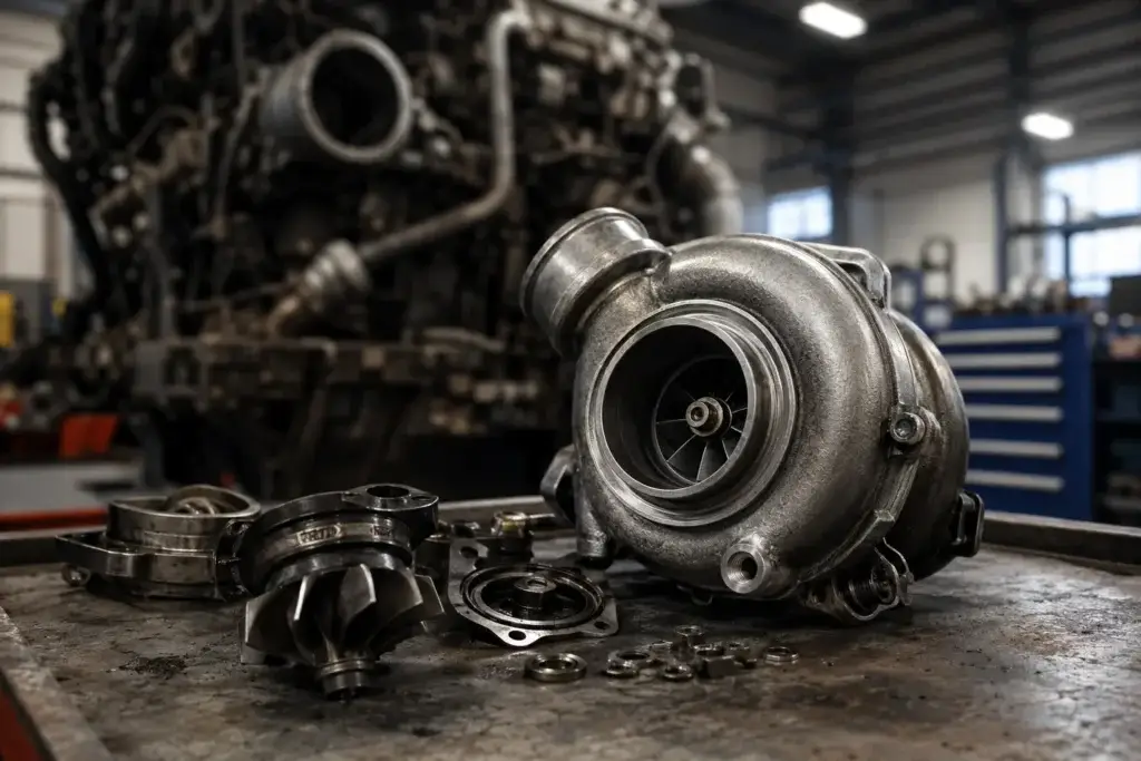
A turbocharger rebuild is a viable option when the core components — the compressor housing, turbine housing, and center housing rotating assembly (CHRA) — are within specification and the damage is limited to the bearings, seals, and thrust components. A professional rebuild involves complete disassembly, cleaning, precision measurement of all rotating components, replacement of bearings, seals, thrust washers, and snap rings, reassembly to OEM clearances, and dynamic balancing on specialized equipment. The critical qualifier here is professional: a rebuild performed without in-house balancing equipment, proper measurement tools, and access to OEM-specification component kits introduces more risk than it eliminates.
For standard fixed-geometry turbochargers on Class 6–8 engines where the housing components are sound, a rebuild from a qualified specialist can deliver reliable service at meaningful savings compared to OEM replacement. The availability of quality rebuild components is a key factor — some platform-specific turbocharger assemblies have excellent parts availability that makes rebuilding cost-effective; others do not.
When Replacement Is the Better Call
Replacement with a new or certified remanufactured unit is the appropriate choice in several scenarios: when the housing components show contact scoring or structural damage that cannot be corrected through rebuild; when the damage is severe enough that rebuild cost approaches replacement cost; when fleet downtime urgency makes a ready-to-install unit more economical than rebuild turnaround time; or when the turbocharger is a VGT unit requiring complex actuator calibration that a general shop is not equipped to perform.
For VGT applications on modern emissions-compliant engines — Cummins ISX, Volvo D13, Detroit DD15 — the complexity of the variable geometry mechanism and the requirement for electronic actuator calibration after replacement make a low-quality rebuild a false economy. The cost difference between a marginal uncertified rebuild and a properly calibrated certified reman unit is typically small relative to the cost of a second turbo failure or downstream DPF damage from improperly calibrated boost control.
Cost Reference: Heavy-Duty Turbocharger Service
Understanding current cost ranges helps fleet managers and owner-operators evaluate quotes and make informed decisions:
2025–2026 Heavy-Duty Turbocharger Service Cost Ranges
- VGT professional rebuild (certified specialist): $1,200–$2,000 depending on platform and component condition
- Fixed-geometry rebuild: $800–$1,500 for most Class 6–8 applications
- Certified remanufactured VGT unit (Cummins ISX, Volvo D13): $2,099–$4,500 for the part alone
- New OEM VGT through dealership: $6,000–$10,000+ depending on platform
- Labor (installation, typical flat-rate): $500–$800 for most HD applications
- VGT electronic calibration (where required): Additional $200–$400 depending on shop and platform
- Cost of catastrophic failure deferred too long: Full engine rebuild cost of $15,000–$40,000 if turbo debris enters the engine or DPF is destroyed by improper boost control
Key Recommendation
Always replace the oil feed line, oil drain line, and oil filter as part of any turbocharger replacement. The combined cost of these parts is typically $30–$80 depending on the application. Skipping this step to save on parts cost is the leading cause of premature failure in replacement turbochargers — the contaminated or restricted feed line that contributed to the original failure remains in place and destroys the new unit.
Free Professional Fleet Tools
Cost calculators, fault code lookup, maintenance planners, and more — built for owner-operators, fleet managers, and diesel techs. No signup required.
Turbocharger Replacement: The Correct Installation Sequence
Even a correctly diagnosed root cause and a quality replacement unit can result in premature failure if installation does not follow the correct sequence. This section covers the installation steps that protect the replacement unit and are most frequently skipped in time-pressured shop environments.
Pre-Installation Checklist
- Flush the oil system. If the failure was oil-related — starvation, contamination, or coking — drain and refill the engine oil and replace the oil filter. Use a cleaning flush if contamination was severe. Inspect and clean or replace the turbo oil feed line and return line.
- Inspect and clean the oil inlet. Check the oil inlet port on the center housing for carbon deposits that could restrict initial oil flow. Even a partial blockage is enough to cause oil starvation during the critical first minutes of operation.
- Pre-lubricate the replacement turbo. Before installation, pour clean engine oil into the oil inlet port of the new turbocharger and rotate the shaft by hand to distribute oil throughout the bearing assembly. This eliminates the dry-start condition that damages bearings before the oil system pressurizes.
- Install new gaskets, not reused ones. Reused turbo mounting gaskets and oil line gaskets are a common source of post-installation oil leaks and air leaks that cause immediate diagnostic confusion.
- Use OEM torque specifications. Turbocharger mounting fasteners and oil line fittings are torqued to specific values that prevent leaks and thermal warping; do not estimate.
Post-Installation Break-In Procedure
After installation, crank the engine without starting — most diesel platforms allow disabling fuel delivery temporarily — to build oil pressure and allow the oil system to prime the turbo feed line before the first start. On the first start, idle the engine for two to three minutes before applying any load. Monitor for oil leaks at the feed and return lines, unusual noises from the turbo, and boost readings on the scanner. Do not load the engine heavily until it reaches full operating temperature and oil is fully circulated. For VGT-equipped engines, perform the actuator calibration procedure required by the OEM before returning the truck to service.
Preventive Maintenance: Protecting Turbochargers in Fleet Operations
Turbocharger longevity in heavy-duty fleet applications is primarily a function of oil system discipline and driver behavior — not parts quality. Per CVSA inspection standards, inoperative or failed forced induction systems are a citation condition during roadside inspection; proactive PM prevents both roadside out-of-service conditions and the far higher cost of in-service failures. The following practices protect turbochargers across the fleet life cycle:
Oil Change Intervals and Oil Quality
Oil viscosity and API service category are not interchangeable with OEM specifications. Cummins ISX and X15 engines require oil meeting Cummins CES 20086 specification; Detroit DD13/DD15/DD16 engines specify DFS 93K222. Using off-specification oil — even if it meets the basic API CK-4 category — can result in inadequate high-temperature film strength at turbocharger bearing temperatures, which regularly exceed 300°F during sustained operation. Follow OEM-specified drain intervals using oil analysis as a guide for extending intervals on trucks demonstrating clean oil condition.
Cooldown Procedure Before Shutdown
Hot shutdown — turning off the engine immediately after sustained hard operation — is the single most controllable cause of premature turbocharger failure in fleet operations. The turbocharger bearing housing retains heat for several minutes after engine shutdown; without oil flow to carry away that heat, residual oil in the feed line bakes into carbon deposits that progressively restrict future oil flow. Fleet operators should build a minimum 30-second idle into driver shutdown procedures. This simple practice costs nothing and protects a $2,000–$5,000 component.
Air Filter and Intake System Maintenance
Air filter maintenance intervals in dusty operating environments — construction, agriculture, unpaved roads — should be shortened significantly from OEM highway maintenance schedules. The Technology and Maintenance Council (TMC) recommends monitoring air filter restriction indicators at every PM service rather than relying on mileage or hours intervals alone for variable-duty-cycle fleets. Additionally, inspect all intake boot clamps and piping connections at each PM service — vibration-related clamp loosening is common on vocational trucks operating off-highway and allows dust ingestion that progressively destroys compressor wheels.
EGT Monitoring in High-Load Applications
Sustained high exhaust gas temperatures from aggressive performance tuning, consistent overloading, or high-altitude mountain haul applications accelerate turbine wheel and seal wear. Monitoring exhaust gas temperature via the EGT sensor (standard on most modern emissions-compliant engines and visible in scanner live data) provides an early warning of operating conditions that are degrading turbocharger life. Consistent EGT readings at or near the engine's protection threshold during normal operation indicate an underlying issue — restricted airflow, excessive load, improperly calibrated fueling — that should be addressed rather than accepted as normal.
Frequently Asked Questions
What are the first signs of turbocharger failure in a diesel truck?
The earliest detectable signs of turbocharger failure in a diesel truck are typically increased oil consumption and subtle power loss during acceleration, often appearing four to eight weeks before visible exhaust smoke or fault codes. Other early indicators include a faint high-pitched whine under load that wasn't present before, slightly longer spool-up time before the engine comes on boost, and oil film inside the compressor housing that appears heavier than the normal light mist from the crankcase ventilation system. Most drivers adapt to gradual power loss without recognizing it — which is why fleet PM programs should include periodic boost pressure verification with a scan tool rather than waiting for a driver complaint.
How do I know if my turbo is bad or if it's a boost leak?
The fastest way to distinguish turbocharger failure from a boost leak is a charge air system pressure test. Pressurize the system between the compressor outlet and the intake manifold with shop air at 20–30 PSI with the engine off; a boost leak will reveal itself as escaping air audible or detectable with soap solution at any connection, boot, or intercooler end tank. If the pressure test holds cleanly, the underboost condition is inside the turbo itself — inspect for shaft play, compressor or turbine damage, and VGT vane function. A boost leak is far less expensive to repair than a turbocharger; always pressure-test the charge air system before any turbo decision.
Can a turbocharger be cleaned to fix VGT vane sticking?
Yes, in many cases VGT vane sticking caused by carbon and soot buildup can be resolved through professional cleaning without replacing the entire turbocharger. This requires removing the turbocharger, disassembling the VGT mechanism, using appropriate chemical or mechanical cleaning methods to remove carbon deposits from the vane channels and actuator linkage, and verifying the mechanism moves freely through its full range of motion before reassembly. The success of cleaning depends on the severity of the buildup and whether the vane components or actuator linkage have sustained mechanical damage from operating in a stuck condition. A turbo specialist can assess the cleaning viability after removal; do not attempt VGT cleaning without full disassembly and proper tooling, as partial cleaning can dislodge carbon fragments into the bearing system.
How long does a heavy-duty turbocharger last?
A properly maintained heavy-duty turbocharger on a Class 6–8 diesel engine should last 300,000–500,000 miles or more under normal operating conditions. Many high-mileage applications report turbos lasting the full service life of the engine (800,000–1,000,000+ miles) when oil change intervals are rigorously maintained, cooldown procedures are followed, and air filtration is kept clean. Early failure — before 200,000 miles — almost always traces to one of the three preventable root causes: oil starvation, oil contamination, or foreign object damage. When a turbocharger fails prematurely, the diagnostic process described in this guide is essential to identify and correct the cause before installing a replacement.
What fault codes are associated with turbocharger failure on heavy-duty diesels?
Common turbocharger-related fault codes include SPN 102 (Boost Pressure) with FMI codes indicating low boost (FMI 1 or 18) or high boost (FMI 0 or 16), SPN 1127 (Turbocharger 1 Boost Pressure) on some platforms, and VGT-specific codes for actuator position or response faults (platform-specific — consult OEM diagnostic documentation for Cummins, Detroit, or PACCAR applications). Importantly, these codes confirm the ECM detected an out-of-range condition in the boost system — they do not confirm the turbocharger is at fault. Boost leaks, failed MAP sensors, restricted air filters, and stuck EGR valves all generate the same codes. Always use the systematic diagnosis procedure described in this guide before acting on boost fault codes alone.
Should I idle my diesel truck after driving to protect the turbo?
Yes, particularly after sustained hard operation — loaded highway driving, mountain grades, heavy towing, or vocational duty cycles. A minimum 30-second idle after hard use allows oil circulation to continue cooling the turbocharger bearing housing before oil flow stops. After extreme operation (sustained grades at high load, extended high-speed runs), two to three minutes of idle is preferable. This single practice, consistently applied across the fleet, is the highest-return intervention for protecting turbocharger service life in heavy-duty operations. Modern diesel engines with turbo timers or idle management systems can be configured to automate this cooldown period.
Conclusion
Turbocharger failure diagnosis in heavy-duty diesel applications is a systematic process — not a symptom-matching exercise. The three root causes (oil starvation, contamination, and FOD) are responsible for virtually all failures, and every one of them leaves behind physical evidence in the form of characteristic damage patterns that guide the correct repair. The most expensive mistake in turbo service is replacing the unit without identifying and correcting the cause — an error that costs the fleet the price of a second turbocharger in addition to the first, plus the downtime for both repairs.
At Heavy Duty Journal, we've consistently found that the fleets with the lowest turbocharger failure rates are those who treat oil system discipline — change intervals, oil specification compliance, cooldown procedures, and feed line inspection — as non-negotiable PM items rather than optional practices. The turbocharger is the hardest-working component on the diesel engine; it deserves the maintenance rigor that reflects that reality.
Share This Diagnosis Guide With Your Shop Team
If your technicians are seeing repeat turbocharger failures, this root cause framework and installation checklist can help them break the cycle — forward it to your lead tech or service manager before the next turbo job comes through the door.