
By Michael Nielsen, Editor & Publisher | 15+ Years in Diesel Repair
Last Updated: April 2026
📖 Estimated reading time: 20 minutes
PTO system maintenance on trucks is one of the most overlooked disciplines in vocational fleet management — and one of the costliest to ignore. Power take-off systems are among the most misunderstood components in commercial trucking until they fail. When a PTO goes down on a dump truck, a vacuum excavator, or a municipal service vehicle, the entire unit becomes unproductive regardless of how well the drivetrain performs. For fleet managers and diesel technicians responsible for vocational equipment, a solid understanding of PTO system maintenance for trucks is not optional. It directly determines uptime, repair costs, and whether your crews make it to the jobsite ready to work. This guide covers everything from initial installation through daily operation, scheduled maintenance, and hands-on troubleshooting.
Key Takeaways
- Spec before you buy: Matching the PTO to your transmission make, model, and application torque requirements is the single most important step — wrong spec leads to early failure and potential transmission damage.
- Tie maintenance to the transmission: PTOs share transmission fluid for lubrication; your PTO inspection schedule should mirror your transmission PM intervals, not stand alone.
- Use the divide-and-conquer method: When troubleshooting a PTO failure, start at the end of the system — the equipment being powered — and work back toward the PTO unit itself to isolate faults efficiently.
- Air system health drives PTO reliability: Air-shift PTOs depend on clean, properly pressurized air; neglecting air dryer maintenance creates PTO solenoid and cylinder failures at disproportionately high rates.
- Lockout/tagout before any service: PTO output shafts are a serious entanglement hazard — OSHA’s control of hazardous energy standard (29 CFR 1910.147) applies to all PTO service work.
What Is a PTO System and How Does It Work?
A power take-off (PTO) is a mechanical gearbox mounted to a truck’s transmission, transfer case, or engine that extracts rotational power and redirects it to work-performing equipment outside the drivetrain. In practical terms, it is the system that turns one engine into two: the engine propels the truck, and through the PTO, it simultaneously — or alternatively — powers hydraulic pumps, pneumatic blowers, vacuum systems, compressors, winches, and generators.
The SAE J704 standard governs PTO mounting flange dimensions for six- and eight-bolt truck transmission-mounted power take-offs, establishing the interface between the PTO unit and the transmission housing. Once a PTO is mounted and engaged, its output shaft rotates at a speed determined by the transmission gear selected and the PTO’s internal gear ratio. Output RPM on most Class 7 and Class 8 applications typically ranges from 800 to 1,500 RPM at governed engine speed, with gear ratios commonly expressed as a percentage of engine RPM — such as 100% (1:1), 87%, or 62%. That ratio must match the rated input speed of whatever the PTO is driving, whether that is a hydraulic pump, a blower, or a generator head.
Engagement happens through one of three mechanisms: mechanical (sliding gear via a manual lever and linkage rod), air-shift (a pneumatic cylinder actuated by a dash-mounted switch that energizes a solenoid valve), or electric-shift (a 12V or 24V electric actuator). On Class 7 and Class 8 commercial trucks, air-shift is the dominant design because these vehicles already operate a pressurized air system for braking. The engagement mechanism selected affects how the PTO should be maintained and what typically goes wrong.
Types of PTO Systems for Commercial Trucks
Not all PTOs are built the same, and the right type depends entirely on what the truck needs to do. Misidentifying the required PTO type is one of the costliest mistakes in the vocational upfitting process.
Transmission-Mounted PTOs
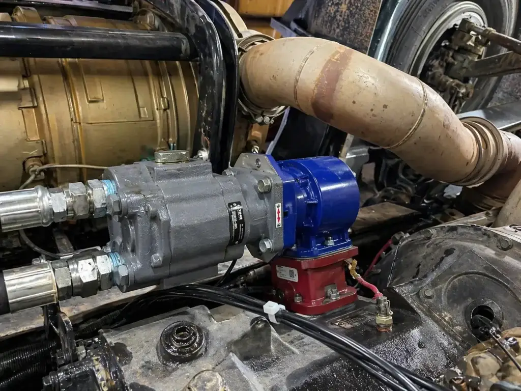
The most widely used configuration in commercial trucking, transmission-mounted PTOs bolt directly to an opening on the side — driver’s side, passenger’s side, or bottom — of the main transmission housing. They draw power from the transmission’s countershaft gears and redirect it to an output shaft that can be coupled directly to a hydraulic pump or connected via a driveshaft to equipment further down the chassis. Most transmission-mounted units operate only when the truck is stationary, making them well-suited to blowers, compressors, hydraulic cranes, and tank unloading systems in dry bulk and petroleum fleets. Some newer automated transmissions allow mobile PTO operation, enabling drivers to maneuver the truck with the PTO engaged — a significant operational advantage in tight delivery environments.
Split-Shaft PTOs (SSPTOs)
Mounted between the transmission and the rear differential, split-shaft PTOs divide the truck’s driveshaft into two segments. One path continues to the drivetrain; the other routes power to the PTO-driven equipment. This design allows simultaneous operation of the vehicle and the PTO — the driver can move the truck while the equipment is working. SSPTOs are capable of handling higher torque loads than standard transmission-mounted units, making them the preferred choice for hydrovac excavators, concrete pumpers, and high-pressure municipal cleaning trucks. The tradeoff is added drivetrain complexity, weight, and installation cost.
Flywheel / Engine-Mounted PTOs
Flywheel-mounted or engine-mounted PTOs bolt directly to the rear of the engine flywheel housing. Because they draw power directly from the engine rather than through the transmission, they deliver power whether the truck is moving or stationary and can access a greater share of available engine torque. Cement mixers, refuse trucks, and vocational vehicles that require continuous drum or equipment rotation — even during idle or transport — commonly use this configuration. Fire apparatus and vehicles requiring full-engine-power auxiliary systems may use a sandwich-type split-shaft unit that mounts between the engine and transmission, capable of delivering up to the complete rated engine power to the PTO output.
Electric PTOs (ePTOs)
Electric PTOs use a battery or motor-generator system rather than a mechanical gear connection to power auxiliary equipment. They generate electricity from the engine or battery pack and route it to electric motors driving the auxiliary systems. ePTOs produce significantly lower emissions than mechanical alternatives, reduce idle time, and can operate when the engine is off on hybrid or battery-electric platforms. Municipal fleets, utility service vehicles, and refuse trucks are adopting ePTO systems as zero-emission zone compliance requirements expand. Upfront cost remains higher than mechanical PTOs, and battery range limitations apply in continuous-duty applications, but the maintenance profile is typically simpler — fewer gears, seals, and fluid systems to manage.
| PTO Type | Best Applications | Mobile Operation? | Key Consideration |
|---|---|---|---|
| Transmission-Mounted | Dump trucks, tank trailers, cranes, blowers | Limited / Model-dependent | Must match transmission make/model exactly |
| Split-Shaft (SSPTO) | Hydrovac, concrete pumpers, municipal | Yes | Higher cost, higher torque capacity |
| Flywheel / Engine-Mounted | Cement mixers, refuse, fire apparatus | Yes | Accesses full engine torque, higher complexity |
| Electric (ePTO) | Municipal, utility, zero-emission zones | Yes | Higher upfront cost, simpler fluid maintenance |
Selecting the Right PTO: The Four T’s Framework
Choosing the wrong PTO does more than waste money on the unit itself. An undersized or mismatched PTO can fail early, take out the transmission with it, and send metal debris throughout the hydraulic system — a scenario that easily turns a few-thousand-dollar PTO replacement into a six-figure drivetrain overhaul. The industry approach to avoiding this outcome starts with four fundamentals known in the upfitting trades as the Four T’s.
The Four T’s
The industry-standard framework for PTO specification in vocational trucking
Truck: Start with the truck’s build spec sheet from the OEM. This identifies whether a PTO prep package was factory-installed — which typically includes pre-routed wiring, a chassis opening, and structural provisions for PTO mounting. Trucks without a prep package require additional labor and may present clearance challenges inside the chassis. Check available space around the transmission opening before selecting a PTO housing size.
Transmission: The transmission make, model, and opening type must be known before any PTO can be specified. Different transmissions offer different opening configurations — driver’s side, passenger’s side, top mount, bottom mount, or rear. Each opening provides a different percentage of engine RPM output. Automated transmissions from major OEMs handle PTO engagement requests through the transmission control module to prevent system damage, which changes how engagement controls are wired and programmed.
Type: Given the truck platform and transmission, determine which PTO type is physically compatible and mechanically appropriate. Consider how the PTO will be shifted — by air, cable, electric-over-air, or electric-over-hydraulic — and whether mobile PTO operation is required. The shift method determines which engagement controls must be installed in the cab and what auxiliary systems (air or electrical) the PTO will depend on.
Task: Define the application requirements with precision. What is the gallons-per-minute (GPM) demand of the hydraulic pump? What working PSI is required? What is the maximum PSI? What engine RPM will the PTO operate at? These numbers determine the torque and horsepower the PTO must handle. The recommended torque capacity for the PTO is calculated using the application’s torque demand multiplied by a service factor — 1.5 for light-duty, 1.75 for medium-duty, and 2.0 or above for heavy-duty or high-impact applications.
Additionally, the PTO output shaft RPM must be matched to the input speed specification of whatever it is driving. A hydraulic pump rated for 1,000 RPM connected to a PTO outputting 1,400 RPM will destroy the pump prematurely. Confirm RPM compatibility before purchase, and verify that the transmission gear selected for PTO operation yields the correct output ratio.
PTO Installation: Step-by-Step Guide for Technicians
⚠️ Safety Warning
PTO output shafts are a serious entanglement hazard. Before performing any installation, adjustment, or service work on a PTO system, apply lockout/tagout procedures per OSHA 29 CFR 1910.147 — the Control of Hazardous Energy standard. Ensure the engine is off, the parking brake is set, and the driveshaft is secured before working near any rotating components. Never reach around an exposed PTO shaft. Guards and shields must be reinstalled before returning the vehicle to service.
Gather Transmission Specifications
Obtain the transmission make, model number, and the specific PTO opening you will use (location and bolt pattern). Confirm whether a PTO prep package was ordered with the truck. Review the build spec sheet to identify any chassis clearance restrictions. Determine the output shaft RPM for the intended opening based on the transmission’s PTO RPM chart — most OEMs publish this data by opening position and engine speed.
Verify Fitment and Prepare the Opening
Clean the transmission PTO opening thoroughly. Inspect the gear teeth in the opening for wear or damage — installing a new PTO against a worn countershaft gear will shorten the life of both components. For trucks without a prep package, deforming the floorboard to accommodate the PTO shift lever is common; plan for this before starting. Confirm that the PTO housing does not contact any surrounding chassis components when fully installed.
Mount the PTO and Torque Bolts to Spec
Install the PTO gasket and mount the unit to the transmission opening. Torque mounting bolts to the specification in the PTO installation manual — this is critical. Undertorqued bolts allow the PTO to shift on the transmission housing over time, and even 0.5 mm of misalignment at the mounting flange can produce gear whine and accelerated wear on both the PTO and the transmission. Record the torque specification and verify it at first PM service.
Install the Output Shaft and Couple to Driven Equipment
Grease the PTO output shaft before coupling to the hydraulic pump or driveline. When possible, mount the hydraulic pump directly to the PTO output face — this eliminates the driveshaft entirely, reducing alignment complexity and eliminating one additional failure point. If a driveline is required to reach equipment further along the chassis, install proper brackets, ensure correct driveshaft angles, and verify that the driveshaft is properly guarded per OSHA requirements.
Wire Controls and Verify Cab Interface
The PTO can only be engaged from controls inside the cab. Proper wiring of the rocker switch, solenoid, indicator light, and any interlocks is essential. Follow the wiring schematic in the PTO owner’s manual — these are typically clear enough for a methodical technician to work from. After wiring is complete, test each control function from the cab before connecting any driven equipment: verify that the indicator light illuminates when the PTO is engaged, and confirm that the PTO disengages cleanly when commanded.
Commission and Establish Maintenance Schedule
Run the PTO under light load for the first 10–20 hours of operation and monitor for unusual heat, noise, or leaks. A newly installed PTO running warm during break-in is normal; temperatures above 220°F measured at the bearing carrier by infrared thermometer indicate a problem. Set the PTO maintenance schedule before the truck re-enters service. Tie PTO inspections to the same PM events as the transmission and do not let them become a separate, easily missed item.
Stay Current on Truck Systems and Fleet Maintenance
Get practical diesel maintenance guides, troubleshooting resources, and industry updates delivered to your inbox — free, every time we publish.
PTO System Maintenance for Trucks: Schedules and Inspections
The most reliable principle for PTO system maintenance on trucks is this: the PTO shares transmission fluid for internal lubrication, so think of the PTO and the transmission as one system, not two. Parker Chelsea’s guidance, which aligns with recommendations from other major PTO manufacturers, is that the PTO maintenance schedule should be tied directly to the transmission’s preventive maintenance schedule. For fleets using Allison Transmission units, fluid and filter changes are recommended at 75,000 miles for the filter and 300,000 miles for the fluid, with the PTO manufacturer’s service manual providing any additional specific requirements.
Beyond fluid, there are four areas every technician should address at each PM event involving a PTO-equipped truck.
Visual Inspection: The Foundation of PTO Health
A solid visual inspection takes five minutes and finds more problems than any other PTO maintenance task. Walk the entire PTO from the mounting flange to the output shaft and look for three things: physical damage to the housing or surrounding plumbing and wiring, evidence of leaks or seepage at the mounting gasket or output shaft seal, and any signs that the unit has shifted on the transmission housing. Remember that the PTO mounts directly to the transmission, so any fluid seeping from the PTO is likely transmission fluid — a minor leak found at a PM visit is far cheaper to address than a blown seal found pooling on a jobsite.
Driver input is an underutilized resource here. Drivers know what their PTO sounds like during normal operation and can often identify the early-stage changes in engagement feel, response speed, or operating noise that precede a failure. Build driver reporting into your PM process and keep notes in each truck’s file. The driver who notices “it takes a second longer to engage” has given you an early warning that is worth tracking.
Mounting Bolt Torque Verification
Mounting bolt torque verification should occur at every oil change or PM service on any PTO-equipped vehicle. The bolts holding the PTO to the transmission housing have specific torque requirements — found in the PTO installation manual — to maintain proper backlash and prevent the unit from shifting under load. This takes a torque wrench and two minutes. The consequences of skipping it can include gear whine, gear damage, and mounting flange distortion that necessitates removing the PTO from the truck entirely to assess internal damage.
Gear Oil and Internal Inspection
If the PTO is ever removed from the transmission for any reason, perform a visual inspection of the gears and internal components without fully disassembling the unit. Look for pitting, spalling, or unusual wear on gear teeth. Spalled gear fragments that enter the transmission fluid are an accelerating failure — they abrade bearing surfaces and contaminate the fluid throughout the system. Catching gear damage early during a planned PTO removal is far less costly than discovering it after the fragments have done secondary damage.
Engagement System Inspection
Inspect the engagement system components — cables, air valves, solenoids, and electrical connections — for smooth operation and signs of wear. On air-shift units, check air lines for moisture contamination or damage. Air-shift PTOs on trucks with degraded air system maintenance experience solenoid and cylinder failures at disproportionately higher rates. Maintaining the truck’s air dryer and checking for moisture in the air system is a PTO maintenance task, even though it may not appear on the PTO service card. On cable-shift units, inspect the cable for kinking or binding along its entire length and verify that the shift lever travels fully to the engaged detent position.
PTO Maintenance Quick Reference
- Every PM event: Visual inspection of housing, seals, wiring, and plumbing; check for leaks and physical damage
- Every oil change: Verify mounting bolt torque to specification
- Every 3 months: Inspect engagement system (cables, air lines, solenoids, electrical connections)
- Every 50,000 miles or annually: Gear oil check for contamination or metal particles
- At any PTO removal: Visual gear and bearing inspection without full disassembly
- Break-in period (first 10–20 hours): Monitor temperature, noise, and leaks; normal run-warm is expected
- Severe-duty cycles (refuse, construction): Shorten all intervals; inspect monthly at minimum
220°F
The bearing carrier temperature threshold — measured by infrared thermometer — above which a PTO is considered to be overheating. Common causes include too much or too little grease, excessive sideload, or a continuous high-load duty cycle without adequate cooling.
The HDJ Perspective
Fleet managers often treat the PTO as an afterthought on the PM schedule — a component that only gets attention when something breaks. That approach is expensive. The shops and fleets with the best PTO uptime records are the ones who’ve integrated PTO inspection into their transmission PM workflow so tightly that it’s invisible: technicians check the PTO mounting bolts every time they change the transmission filter, and driver reports on engagement feel feed directly into the maintenance file. As ePTO adoption grows in municipal and utility fleets, the maintenance profile changes — fewer fluid and gear concerns, more focus on electrical systems and battery health — but the fundamental discipline of scheduled inspection doesn’t change. The fleets that will maximize ePTO uptime will be the ones that adapt their existing PM culture to the new technology, not the ones waiting for something to fail before they look.
PTO Troubleshooting: Diagnosing Common Failures
PTO troubleshooting requires patience, system knowledge, and a structured approach. The most effective diagnostic method in the field is what the industry calls the divide-and-conquer approach: study the system from start to finish, identify specifically what is not working, and isolate the fault by starting at the end of the system — the equipment being powered — and working back toward the PTO.
Before assuming the PTO is the source of a problem, verify that the issue is not with the driven equipment or the driveline connecting them. Ask: Is the auxiliary equipment not rotating at all? Not building pressure? Leaking? Showing no flow? Each symptom points to a different part of the system. A hydraulic pump that will not build pressure could be a pump failure, a relief valve issue, or a blocked filter — not a PTO fault at all.
Common PTO Symptoms and Initial Diagnostic Steps
| Symptom | Likely Cause | First Diagnostic Step |
|---|---|---|
| PTO will not engage — indicator light off | Electrical fault, blown fuse, no air pressure | Check indicator bulb first, then fuse, then voltage at solenoid |
| PTO will not engage — indicator light on | Indicator/pressure switch fault, PTO mechanical issue | Check air or hydraulic pressure at activation port with gauge |
| Excessive noise / gear clatter at idle | Partial engagement, shift linkage misadjustment, worn gears | Verify shift lever reaches full engaged detent; check linkage for binding |
| Gear whine under load | Mounting flange misalignment, loose mounting bolts | Check and retorque mounting bolts; inspect mounting flange for shift |
| Overheating PTO | Insufficient lubrication, excessive load, wrong gear ratio | Verify transmission fluid level; check RPM ratio vs. pump input spec |
| Fluid leaking from PTO | Worn output shaft seal, damaged mounting gasket | Identify leak origin (mounting face vs. output shaft); check bolt torque |
| PTO will not disengage | Damaged clutch collar, stuck shift cover, wiring fault | Disconnect hydraulic pump and check if PTO shaft still spins |
Electrical Troubleshooting: Air-Shift and Electric-Shift Systems
Electrical faults are among the most common and most misdiagnosed PTO problems on commercial trucks. A structured approach prevents technicians from replacing expensive components unnecessarily.
Begin with the indicator light. If the light fails to illuminate when the PTO switch is activated, and the light is a separate unit from the rocker switch, test the bulb first — a burned-out bulb has sent technicians down hours of unnecessary diagnostic work. If the bulb is good, check for power at the rocker switch and verify that the fuse protecting the PTO circuit is intact. With the switch on, voltage at the solenoid connector should read approximately 12V (or 24V on a 24V system). No voltage at the solenoid connector means the fault is in the circuit between the switch and the solenoid — look for broken or corroded wiring, a failed relay, or a bad ground connection.
On air-shift units, if voltage is confirmed at the solenoid but the PTO does not engage, the problem shifts to the pneumatic side. Tee a pressure gauge into the activation port on the PTO. With the switch on, activation pressure should reach at least 70–90 PSI for air-shifted units. Low pressure points to the truck’s air system — a failing air dryer, a moisture-clogged line, or a degraded air supply to the PTO circuit. If activation pressure is confirmed but the unit still will not engage, the pneumatic cylinder inside the PTO housing is likely damaged and the PTO will need to come off the transmission for internal inspection.
Mechanical Troubleshooting
Mechanical PTO faults typically manifest as noise, partial engagement, or inability to hold the engaged or disengaged position. On mechanical-shift units, shift linkage misadjustment is a leading cause of partial engagement — the gear clatter it produces at idle is distinctive. Adjustment involves confirming that the shift lever travels completely to the engaged detent position and that the linkage rod has no kinks or binding points along its length. Inspect for a missing woodruff key on the output shaft — this is a surprisingly common miss during rushed installations that causes the output shaft to spin freely without driving the load.
Mounting bolt looseness is a mechanical fault that masquerades as a gear problem. Even minor housing movement on the transmission cover produces gear whine and accelerated wear that can look like internal gear damage on inspection. Always verify and retorque mounting bolts before condemning internal components. If bolts are found loose and the whine persists after retorquing, remove the PTO and inspect the mounting flange and transmission cover opening for distortion or wear.
For any PTO fault involving metal contamination — fragments in the gear oil, debris in the hydraulic system, or unusual scoring on the gears — the repair scope expands beyond the PTO itself. Metal debris circulating through a hydraulic system will damage pumps, control valves, and cylinders. The entire hydraulic system must be flushed and all filters replaced before returning the equipment to service. Using old or recovered parts during this process is a false economy that accelerates repeat failure.
Free Professional Fleet Tools
Cost calculators, fault code lookup, maintenance planners, and more — built for owner-operators, fleet managers, and diesel techs. No signup required.
PTO Operating Best Practices for Fleet Managers
Even a correctly specified and properly installed PTO will fail ahead of schedule if it is operated incorrectly. Operator education is part of the maintenance program, not separate from it — and in fleets where drivers change frequently or vehicles are shared across shifts, documented operating procedures are essential.
The most damaging operational habits are abrupt engagement under high engine RPM and excessive PTO cycling. Always engage the PTO at low engine RPM — typically idle or just above — and gradually increase engine speed to reach the operating RPM. Sudden engagement at high RPM subjects the gear teeth to shock loads that chip and spall gear faces and shorten bearing life. On automated transmissions with electronic PTO control, the transmission management system handles engagement timing, but on manual and mechanical-shift units, operator technique matters significantly.
Excessive cycling — repeatedly engaging and disengaging the PTO in rapid succession — generates heat in the clutch components and accelerates wear. In refuse and dump truck operations, emergency or rapid engagement under load is a primary cause of gear spalling. Where the application requires frequent engagement cycles, verify that the PTO selected is rated for the expected duty cycle. A PTO specified for occasional stationary use on a vehicle that ends up cycling it hundreds of times per shift will not reach its rated service life.
Operators should disengage the PTO fully before moving the truck unless the system is specifically rated and configured for mobile PTO operation. Driving with an improperly engaged PTO — or with a PTO that is partially disengaged — creates heat, noise, and gear damage that shortens the unit’s service life substantially. TMC Recommended Practices provide additional operational guidance for vocational truck equipment that complements manufacturer-specific PTO operating instructions.
Consider integrating 49 CFR Part 396 inspection and maintenance practices into pre-trip routines for PTO-equipped vehicles. Drivers should note any changes in PTO engagement response, unusual sounds during operation, or equipment behavior that differs from baseline — and those notes should flow to the maintenance team rather than being dismissed as “just how this truck is.”
Compliance is a secondary consideration that becomes primary when something goes wrong. The FMCSA does not regulate PTO units as independent components, but under 49 CFR Part 393, which covers parts and accessories necessary for safe operation, a PTO-driven hydraulic failure that affects vehicle control — such as a dump bed that cannot lower — creates conditions that can result in out-of-service findings at a CVSA inspection. Document PTO-related defects and repairs in the vehicle maintenance file for compliance continuity.
Key Recommendation
Build a one-page PTO operating procedure card for every PTO-equipped truck in your fleet — engagement sequence, permitted operating RPM, mobile operation status (yes/no), and any application-specific cautions. Laminate it and mount it in the cab. Driver knowledge gaps cost as much as missed PM events over the lifetime of a PTO system.
Frequently Asked Questions
How often should a PTO system be serviced on a commercial truck?
PTO service intervals are typically tied to the transmission’s preventive maintenance schedule. For most commercial trucks, a visual inspection should occur every three months or at each PM service event. Mounting bolt torque should be verified at every oil change. Gear oil inspection — checking for contamination or metal particles — should happen every 50,000 miles or annually, whichever comes first. Trucks operating in severe-duty cycles, such as refuse or construction, should inspect PTOs more frequently. Always follow the specific PTO manufacturer’s service manual for interval requirements, and tie your PTO checks into the same schedule as your transmission fluid and filter changes.
What causes a PTO to not engage on a commercial truck?
A PTO that fails to engage is most commonly caused by an electrical fault, low air pressure, or a mechanical issue. On air-shift units, check that the truck’s air system is supplying at least 70–90 PSI to the PTO solenoid — low or moisture-contaminated air is a frequent culprit. On electrical systems, verify voltage at the solenoid connector (should read 12V or 24V with the switch on), check for blown fuses and faulty relays, and inspect wiring for corrosion or damage. Mechanically, a worn shift collar, bent linkage rod, or damaged clutch pack can prevent engagement. Use the divide-and-conquer method: start at the end of the system and work back toward the PTO to isolate the fault.
What is a split-shaft PTO and when is it used?
A split-shaft PTO (SSPTO) is mounted between the transmission and the rear differential, splitting the driveshaft to route power to both the drivetrain and the PTO-driven equipment simultaneously. Unlike transmission-mounted PTOs — which typically require the truck to be stationary — SSPTOs allow a driver to maneuver the vehicle while the PTO is engaged. This makes them well-suited to high-power applications where the truck needs to move during operation, such as hydrovac excavators, concrete pumpers, and municipal service vehicles. They handle higher torque loads than standard transmission-mounted units but add complexity and cost to the drivetrain.
Can a PTO failure put a truck out of service at a DOT inspection?
The FMCSA does not regulate PTO units as standalone components, but a PTO failure can contribute to an out-of-service finding if it affects a system that impacts safe vehicle operation. For example, a PTO-driven hydraulic system failure on a dump truck that prevents the bed from lowering safely can create conditions evaluated under 49 CFR Part 393, which governs parts and accessories necessary for safe operation. CVSA inspectors assess whether auxiliary equipment powered by a PTO poses a safety hazard. Fleets should ensure that PTO-dependent systems — especially dump beds, crane outriggers, and fifth-wheel slide mechanisms — function correctly before vehicles enter service or undergo inspection.
What is the difference between air-shift and electric-shift PTO engagement?
Air-shift PTOs use air pressure — typically 90 to 120 PSI from the truck’s air supply — routed through a solenoid valve to a pneumatic cylinder inside the PTO housing. This is the dominant design on Class 7 and Class 8 commercial trucks, which already have a pressurized air system for braking. Air-shift units can fail at the solenoid or air cylinder, especially when the truck’s air system is poorly maintained or contaminated with moisture. Electric-shift PTOs use a 12V or 24V electric actuator in place of the air cylinder. They are preferred on lighter vocational platforms or vehicles without a dedicated air system. Electric-shift units are simpler electrically but can be more susceptible to actuator wear in high-cycle applications.
Keep Your PTO Systems Running When It Counts
PTO system maintenance for trucks is not a complicated discipline, but it is one that rewards consistency. The fundamentals are straightforward: spec the right unit for your application using the Four T’s, tie maintenance intervals to your transmission PM schedule, train operators on correct engagement procedures, and apply a structured divide-and-conquer approach when something goes wrong. Fleets that treat the PTO as part of the powertrain — rather than an afterthought bolted to the side of the transmission — see meaningfully better uptime and lower lifecycle costs on their vocational equipment.
As ePTO adoption grows and automated transmission integration becomes standard on new vocational builds, the specifics of PTO maintenance will continue to evolve. The underlying discipline will not.
Found This Guide Useful? Pass It Along.
Share this PTO systems guide with your maintenance team, upfitters, or fleet colleagues. Free, practical resources for diesel technicians and fleet managers — always at Heavy Duty Journal.