
By Michael Nielsen, Editor & Publisher | 15+ Years in Diesel Repair
Last Updated: April 2026
📖 Estimated reading time: 16 minutes
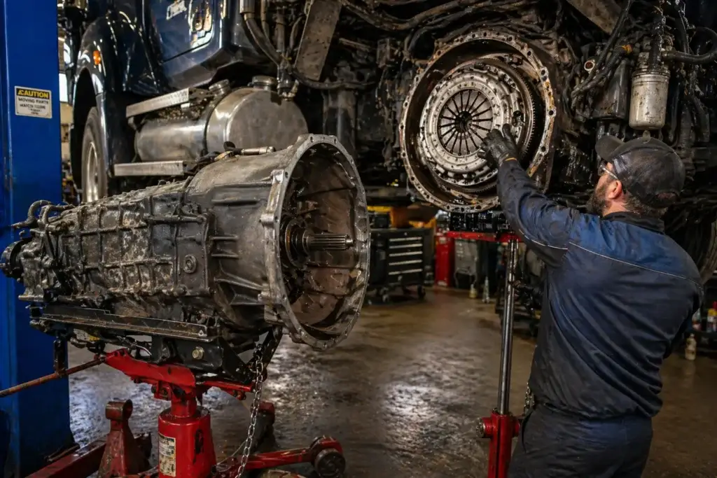
Every heavy duty truck clutch replacement starts with the same fundamental reality: the transmission has to come out. On a Class 8 platform, that means carefully withdrawing 750 to over 1,000 pounds of gearbox on a transmission jack while managing bellhousing clearance, input shaft alignment, and shift linkage — before you’ve even touched the clutch assembly itself. The labor involved is precisely why clutch replacement accounts for some of the highest per-job costs in commercial truck drivetrain maintenance.
Whether you’re a diesel technician running a commercial shop, a fleet maintenance manager overseeing your own technicians, or an owner-operator evaluating the scope of the repair, understanding the complete procedure matters. A properly performed clutch replacement on a line-haul truck should deliver 200,000 to 400,000 miles of reliable service. One completed without flywheel inspection, clutch disc alignment, or proper break-in protocol may not reach 75,000.
This guide covers the complete heavy duty truck clutch replacement process from start to finish: when replacement is the correct call, how to select the right components, the full step-by-step procedure for manual transmission platforms, flywheel inspection criteria, what AMT clutch replacement requires differently, and the post-installation details that determine long-term clutch life.
Key Takeaways
- Labor is 60–70% of total cost: The most cost-effective time for clutch replacement is when the transmission is already removed for another repair — at that point, the incremental cost is almost entirely parts.
- Friction material measurement drives the decision: Replace when the disc wears within 0.020 to 0.030 inches above the rivet heads — don’t wait for slippage symptoms to confirm what a measurement would have caught months earlier.
- Flywheel resurfacing is mandatory at every replacement: A new friction disc installed on an unserviced flywheel surface is one of the most common causes of premature clutch failure in the field.
- Clutch alignment tool is non-negotiable: No substitute exists for the correct alignment tool — a miscentered disc will prevent transmission reinstallation or cause immediate clutch chatter and early failure.
- Break-in protocol matters for longevity: The first 500 miles after installation determine how evenly friction surfaces seat — brief drivers before returning the truck to heavy service.
Understanding the Heavy-Duty Clutch Assembly
Before any technician opens the inspection cover or rolls a transmission jack into position, a clear picture of the clutch system’s components is essential. The clutch assembly in a manual Class 8 truck is not a single part — it’s a system of interacting components, each of which influences the performance and lifespan of the others. A clutch job done without understanding those relationships produces repairs that come back too soon.
The core components include the flywheel, which is bolted to the engine crankshaft and serves as the primary driving surface; the clutch disc (friction disc), which is the replaceable wear element clamped between the flywheel and pressure plate; the pressure plate assembly, which applies spring clamping force to keep the disc engaged during normal operation; and the release bearing (throw-out bearing), which disengages the clutch when the pedal is depressed. The clutch brake is a separate disc mounted on the transmission input shaft that slows shaft rotation to assist gear engagement from a full stop. The pilot bearing centers the transmission input shaft inside the crankshaft bore and is a wear item that must be replaced at every clutch service.
Eaton’s SOLO self-adjusting clutch platform — used extensively on trucks equipped with Eaton Fuller transmissions — incorporates an internal automatic adjuster that compensates for friction material wear over time. Dana Spicer offers comparable systems. Regardless of the specific make or model, the replacement sequence follows the same fundamental path. Confirming which components in the specific truck require replacement — disc only, a complete clutch kit, or disc plus flywheel — before writing the work order directly affects the parts list, expected labor time, and whether the flywheel can remain in the truck or needs to leave the shop for resurfacing.
60–70%
Of total heavy duty truck clutch replacement cost is labor. When the transmission is already out for another repair, the incremental cost to replace the clutch is almost entirely parts — a window that should never be passed up when friction material is near its service limit.
When Heavy Duty Truck Clutch Replacement Is the Right Call
Knowing when a clutch adjustment will restore proper function versus when full replacement is unavoidable is one of the highest-value diagnostic decisions in drivetrain maintenance. Premature replacement wastes parts and labor. Delayed replacement risks flywheel damage that multiplies the total repair cost substantially.
The clearest replacement indicator is direct measurement. Friction material on the clutch disc must be replaced when it wears to within 0.020 to 0.030 inches above the rivet heads. This measurement requires removing the clutch inspection cover — a quick under-truck procedure on a lift that takes minutes when it’s built into the PM workflow. Shops that incorporate friction material measurement into scheduled service intervals will almost never be caught off guard by an in-field clutch failure.
Beyond measurement, several operational symptoms point to replacement rather than adjustment. Clutch slippage — where engine RPM climbs without a proportional increase in vehicle speed — is the most common presentation. It’s especially noticeable when pulling heavy loads uphill or accelerating from a stop under load. A burning odor under heavy demand confirms the friction material is overheating from inadequate clamping force. Clutch chatter during engagement (a rhythmic shuddering as the truck begins to move) can indicate oil contamination on the friction surface, a warped pressure plate, or a glazed flywheel. A dragging clutch — where the clutch fails to fully disengage even with the pedal fully floored — points to hydraulic system failure, worn linkage, or a seized release bearing.
From a fleet cost standpoint, the math is straightforward: a flywheel that cracks from prolonged contact with a slipping disc costs far more to replace than a clutch kit. Labor represents 60 to 70 percent of total clutch replacement cost, which means the most efficient time to schedule replacement is when the transmission is already coming out for another reason — input shaft bearing service, rear main seal work, or transmission overhaul. That window should not be wasted when friction material is near its service limit.
⚠️ Safety Warning
Heavy duty transmissions weigh 750 to over 1,000 pounds. Never attempt to support or maneuver a transmission without a rated heavy-duty transmission jack secured with safety chains — never rely on a jack saddle alone. Additionally, worn clutch friction material on older trucks may contain asbestos. Treat all clutch dust as a potential respiratory hazard and use appropriate PPE including nitrile gloves, safety goggles, and respiratory protection. OSHA’s trucking industry vehicle maintenance regulations require that all general industry safety standards apply to workers performing maintenance on commercial motor vehicles, including clutch replacement.
Required Tools and Parts for the Job
Going into a clutch job without the right equipment wastes time and creates installation errors that are expensive to diagnose later. The clutch alignment tool is the most critical item and is transmission-specific — a tool sized for one input shaft diameter will not work on a different platform. Confirm the correct tool is in the shop before the truck enters the bay.
Standard tooling required for most heavy duty truck clutch replacements includes a heavy-duty transmission jack rated to the specific transmission weight, safety chains, a floor jack for additional chassis support, flywheel housing seal driver set, pilot bearing driver and blind puller set, a torque wrench calibrated to the appropriate foot-pound range, a dial indicator with magnetic base for flywheel runout measurement, penetrating oil for seized bellhousing hardware, and the clutch alignment tool matched to the specific transmission and clutch configuration.
Replacement components for a complete clutch job typically include a new clutch disc, pressure plate assembly, release bearing, clutch brake, pilot bearing, and rear crankshaft seal. The rear crankshaft seal is accessible only when the transmission is out — replacing it during any clutch job eliminates a future R&R on a component that would otherwise require the same transmission-out labor to address separately. Per OSHA’s brake and clutch repair guidance, mechanics should perform clutch work in an area isolated from other shop operations and avoid dry-sweeping or blowing clutch dust with compressed air to prevent fiber dispersal.
Stay Current on Drivetrain Maintenance
Get technical guides, maintenance procedures, and fleet management insights delivered directly to your inbox — free, from experienced diesel professionals.
Heavy Duty Truck Clutch Replacement: Step-by-Step Procedure
The following procedure applies to manual transmission Class 8 trucks. Eaton Fuller, Dana Spicer, and other comparable clutch systems follow this general sequence, though specific torque values, clearance specifications, and tooling requirements vary by truck make, model, and clutch configuration. Always reference your specific OEM service documentation for torque specs before performing any repair.
Prepare and Secure the Vehicle
Move the truck to a level surface with adequate overhead clearance for transmission removal — confirm ceiling height before positioning the vehicle. Apply the parking brake and chock all wheels, both front and rear. On air-brake equipped trucks, verify adequate system pressure is maintained or use wheel chocks rated for the vehicle’s loaded weight. Disconnect the negative battery cable before beginning any disassembly. Note that some cab-over configurations require the cab to be tilted for full access to the bellhousing, depending on the chassis layout — plan accordingly before starting.
Drain Transmission Fluid and Disconnect Linkage
Drain the transmission fluid completely into an approved container. Remove the drain plug and allow sufficient time for the fluid to clear — partial draining causes spillage during transmission removal. Disconnect the gear shift linkage, air lines to the transmission on air-shifted units, speedometer cable or vehicle speed sensor, and all electrical connections including the reverse light switch and neutral position sensor. Photograph or label every connection before removal; transmission reinstallation is far simpler when reconnection is unambiguous. On hydraulic clutch systems, disconnect and cap the clutch hydraulic line at the slave cylinder to prevent fluid loss and contamination of the new friction components.
Remove the Driveshaft
Before loosening any hardware, mark the driveshaft orientation relative to the transmission output flange and the rear axle yoke with a paint marker or scribe. Remounting the shaft 180 degrees off from its original position introduces driveline vibration that can be difficult to diagnose after reassembly and is a common source of unnecessary callbacks. Remove the U-joint straps or flange bolts at the rear axle end first, then slide the driveshaft rearward to disengage the front slip yoke from the transmission output shaft. Support the shaft throughout removal to prevent U-joint stress or damage, and set it aside on a clean surface.
Support and Remove the Transmission
Position the transmission jack under the gearbox and raise it until it just contacts the housing. Secure the transmission to the jack with safety chains — never rely solely on the jack saddle to hold the unit during removal or installation. Remove the rear transmission crossmember or mount bracket. Remove all bellhousing-to-flywheel-housing bolts, working from the outer perimeter inward. With all bolts clear, carefully slide the transmission directly rearward until the input shaft is fully clear of the clutch assembly. Do not allow the unit to tilt or drop during withdrawal — side loading on the input shaft as it exits the disc hub can damage the disc splines, bend the release fork, or crack the pilot bearing bore. Note that some bellhousing configurations use two bolts as alignment dowels; mark their locations for reinstallation.
Remove and Document the Old Clutch Assembly
With the transmission clear, the clutch assembly is fully accessible through the bellhousing opening. Remove the release bearing from the release fork — inspect the fork, cross shaft, and related bushings for wear while they’re accessible, as these components are best addressed now rather than on a separate visit. Remove the clutch brake from the input shaft stub. Before loosening any pressure plate bolts, mark the assembly’s orientation relative to the flywheel — some assemblies have factory balance orientation marks; preserve them. Loosen the pressure plate mounting bolts progressively in a cross pattern, three full turns at a time, to release spring tension evenly without warping the cover. Remove the pressure plate and clutch disc and set them aside for disposal or comparison against the new components.
Inspect and Service the Flywheel
Do not proceed with component installation until the flywheel has been fully inspected and serviced — the next section covers this in detail. While the flywheel is accessible, remove the old pilot bearing using a blind bearing puller and remove the rear crankshaft seal using a seal puller. Clean the seal bore thoroughly and install the new rear seal using the appropriate driver tool to ensure it seats squarely without lip damage. Install the new pilot bearing using the correct driver — never hammer a bearing in with a punch, as this damages the races and creates the conditions for early failure. Send the flywheel for resurfacing or inspection per the criteria below before any new clutch components are installed.
Install the New Clutch Components
Before installation, verify the flywheel surface is clean, dry, and free of all oil, grease, and fingerprint contamination — wear clean gloves during disc handling and keep lubricants away from the work area. Place the new clutch disc against the flywheel, ensuring the correct side faces the flywheel surface (discs are typically marked “flywheel side” or “transmission side” — verify with the component documentation). Insert the clutch alignment tool through the disc hub and into the new pilot bearing, centering the disc precisely. Install the pressure plate assembly over the disc, aligning the factory balance mark with the reference mark made during removal. Thread all mounting bolts by hand, then torque to specification in a star pattern. Eaton typically specifies 40 to 45 ft-lbs for clutch cover mounting bolts, but always verify against the service documentation for your specific configuration. Remove the alignment tool only after all bolts are fully torqued to specification.
Install the Clutch Brake and Reinstall the Transmission
Slide the new clutch brake onto the transmission input shaft before raising the transmission — it cannot be installed after the unit is in position. Raise the transmission on the jack, aligning the input shaft with the clutch disc hub and pilot bearing bore. Advance the transmission forward slowly and steadily. If the input shaft does not enter freely, do not force it — rotate the output flange slightly to walk the shaft splines into the disc hub. Bring the bellhousing flush with the flywheel housing and confirm alignment dowels are properly seated before installing any bolts. Install all bellhousing bolts finger-tight, then torque to specification. Reinstall the crossmember and mount. Reconnect all linkage, electrical connectors, air lines, and hydraulic lines in reverse of removal. Bleed the hydraulic clutch system if applicable. Install the driveshaft in the marked orientation and torque all U-joint hardware to specification. Refill the transmission with the correct fluid grade and quantity per the manufacturer’s specification.
Adjust, Verify Clearances, and Road Test
Reconnect the battery. With the truck idling, check for fluid leaks, transmission warning indicators, and any unusual noises before moving under power. Adjust the clutch pedal free play to 1.5 to 1.75 inches measured at the pedal pad. Verify the gap between the release bearing face and the front face of the transmission is 1/2 to 9/16 inch — this is set at the clutch adjustment mechanism accessible through the inspection cover on the bottom of the bellhousing. Engage each gear from a stationary position to confirm proper engagement and release. Verify clutch brake function: the clutch brake should assist gear engagement only when the pedal is fully floored from a stopped position; it must not engage during normal in-motion shifts. Perform a short road test on a low-traffic route before returning the truck to service. Document all work and post-repair inspection per the requirements of 49 CFR Part 396, Inspection, Repair, and Maintenance, which requires motor carriers to maintain records of all maintenance and repairs on commercial motor vehicles.
Flywheel Inspection Criteria: Don’t Skip This Step
The flywheel is the clutch system’s foundation, and its condition determines whether a new clutch disc performs correctly or fails prematurely. Flywheel inspection is among the most frequently abbreviated steps in clutch replacement — often because the flywheel looks acceptable to the eye when it’s already compromised at the surface level that determines clutch disc seating quality.
The inspection sequence begins with a visual check for heat cracks. These appear as fine radial lines or concentric circles originating from the friction surface zone. A cracked flywheel requires full replacement — no amount of resurfacing makes a cracked unit serviceable. Heat discoloration (blue or dark spots) indicates areas that have been locally overheated, creating surface zones that are harder than the surrounding material. These hard spots prevent the new clutch disc from seating evenly, producing clutch chatter and accelerated wear that will bring the truck back to the shop well before its time.
After the visual inspection, measure flywheel runout using a dial indicator mounted on a magnetic base positioned on the engine block or bellhousing. Place the indicator tip on the flywheel friction surface near the outer diameter and rotate the flywheel one full revolution. Maximum acceptable total indicator runout is typically 0.006 inches — exact limits vary by manufacturer, so confirm the specification for the specific flywheel before accepting or rejecting it. Runout beyond the specified limit indicates warping that will produce chatter and accelerate disc wear. Measure the flywheel housing bore separately with the same technique; maximum housing runout is generally 0.008 inches per most OEM specifications.
If the flywheel passes the crack and runout checks, it should be sent for resurfacing at a machine shop capable of handling commercial vehicle units. Resurfacing removes glazing, minor scoring, and heat spots while restoring the surface finish required for proper friction disc seating. The machine shop will also verify minimum thickness — each resurfacing operation removes material, and every flywheel has a manufacturer-specified discard thickness below which it cannot be used safely. Confirm that dimension is on record before approving the cut. Plan for one to two business days for flywheel resurfacing if an in-house surface grinder is not available, and schedule accordingly to minimize truck downtime.
The HDJ Perspective
After 15 years of observing diesel drivetrain failures, the pattern is consistent: clutch jobs that come back early almost always trace to one of two omissions — a skipped flywheel resurfacing, or a clutch disc installed without an alignment tool. Both shortcuts save roughly 20 minutes in the bay and cost thousands in repeat labor. As AMT adoption accelerates across new fleet orders, manual clutch expertise is becoming a more specialized skill. That’s not a reason to relax procedure discipline — if anything, it raises the standard. The fleets still running manual transmissions in severe-duty applications are doing so deliberately, with high expectations for component longevity. A clutch replacement that doesn’t last is not just a cost problem; it’s a trust problem between the shop and the fleet it serves.
AMT Clutch Replacement: What’s Different
Automated manual transmissions now account for the majority of new Class 8 truck sales, and their clutch systems require a meaningfully different approach to both diagnosis and replacement. Where a manual clutch job relies on pedal feel and direct visual and physical inspection, AMT clutch diagnosis involves fault codes, actuator testing, and software-based calibration sequences that require a diagnostic scan tool and platform-specific OEM software.
Detroit’s DT12 transmission, Eaton’s Endurant series, and Volvo’s I-Shift all use electronically controlled clutch actuators that modulate engagement torque automatically without driver input. When an AMT clutch wears, the system typically flags fault codes before engagement quality visibly degrades — making early detection more predictable than with manual platforms, provided the technician can correctly interpret the fault data and correlate it with actuator position feedback. Fleet Maintenance’s guide to commercial truck clutch service notes that AMTs offer additional diagnostic resolution through sensor data that manual systems are inherently unable to provide — an advantage in planned maintenance environments but a limitation in shops without the necessary diagnostic tooling.
The physical replacement procedure for an AMT clutch follows the same general sequence as the manual procedure above — the transmission must come out, the clutch disc and pressure plate must be replaced, and the flywheel must be inspected and resurfaced. The critical difference is post-installation. AMT transmissions require a clutch calibration procedure using the OEM diagnostic tool to teach the transmission control module the engagement point of the new clutch components. Skipping this calibration step leaves the system operating with engagement parameters calibrated to the worn clutch — producing rough shifts, premature engagement wear, and potential fault codes from the first miles. The calibration typically takes 15 to 30 minutes but is not optional on any AMT platform.
The Technology & Maintenance Council’s Recommended Practices guidelines for commercial vehicle drivetrain maintenance indicate that technicians servicing AMT systems should be proficient in both the mechanical and electronic aspects of the platform. Shops that have not invested in AMT-specific diagnostic tooling will find clutch replacement on these transmissions increasingly difficult to complete correctly — a capability gap worth closing as the industry continues its transition away from fully manual drivetrains.
Free Professional Fleet Tools
Cost calculators, fault code lookup, maintenance planners, and more — built for owner-operators, fleet managers, and diesel techs. No signup required.
Common Clutch Replacement Mistakes and How to Avoid Them
Even experienced technicians make predictable errors on clutch jobs. Most trace back to time pressure, parts substitution, or skipped verification steps. Understanding where these failures occur is the most effective way to prevent them.
Installing without an alignment tool is the single most common installation error in clutch work. The clutch alignment tool exists to center the friction disc hub over the pilot bearing bore so the transmission input shaft can advance cleanly during reinstallation. Without it, the disc will be off-center, and the input shaft will bind or refuse to enter the hub. Some technicians attempt to eyeball the alignment or improvise a substitute — both approaches result in disc misalignment that makes transmission reinstallation difficult, causes hard installation stress on the input shaft, and produces clutch chatter within the first miles of operation. There is no acceptable substitute for the correct tool.
Contaminating friction surfaces during installation is another frequent cause of early failure. Even a partial handprint of grease on the clutch disc or flywheel friction surface creates a localized slip zone that causes chatter and accelerates wear to the surrounding friction material. Wear clean nitrile gloves during all clutch component handling, keep the work area clear of lubricants, and wipe the flywheel surface clean with a brake cleaner-dampened rag immediately before disc installation. Verify the surface is fully dry before proceeding.
Skipping the pilot bearing and rear crankshaft seal replacement is a decision that generates callbacks. The pilot bearing is a wear item that must be replaced at every clutch service — a technician who installs a new clutch kit and leaves the original pilot bearing in place is setting up a future R&R on a job that should have been completed correctly the first time. The rear crankshaft seal carries identical logic: it costs under $30, requires less than 20 minutes to replace, and is accessible only with the transmission removed. Leaving it in service to fail is an economy that makes no practical sense.
Failing to document the repair properly creates compliance exposure for motor carriers. Under 49 CFR Part 396, carriers are required to maintain records of all inspections, repairs, and maintenance performed on commercial motor vehicles. Clutch replacement documentation should include the repair date, odometer reading, all parts replaced by part number, technician identification, and confirmation of a post-repair inspection. Fleets with thorough maintenance records are also better positioned to identify clutch lifespan trends across their fleet by application, route type, and driver, using that data to optimize replacement timing and reduce unplanned downtime.
Frequently Asked Questions
How much does heavy duty truck clutch replacement cost?
Heavy duty truck clutch replacement typically costs between $1,500 and $5,000 when performed at a professional shop, with labor representing 60 to 70 percent of the total. Parts alone — clutch disc, pressure plate, release bearing, clutch brake, and pilot bearing — generally run $500 to $1,800 depending on the truck platform and component tier. Labor is typically billed at 8 to 10 hours for most Class 8 applications. The most cost-effective timing for clutch replacement is when the transmission is already removed for another repair — at that point, the incremental cost is almost entirely parts. Fleets that track friction material measurements at scheduled PM intervals can plan clutch replacement to coincide with other transmission-out work and significantly reduce total repair expenditure.
How long does clutch replacement take on a semi truck?
A professional clutch replacement on a Class 8 semi truck typically requires 8 to 10 hours of labor in a properly equipped shop. This covers transmission removal, flywheel inspection and removal, new component installation and alignment, transmission reinstallation, and final clutch adjustment and road test. An experienced drivetrain technician working in a dedicated bay with the correct tooling and a pre-staged parts kit can complete the job in a single shift. If flywheel resurfacing is required at an outside machine shop, plan for one to two additional business days. Scheduling a pre-removal clutch inspection — including friction material measurement — before the truck enters the bay eliminates unexpected delays from parts that weren’t ordered in advance.
What are the signs that a heavy duty truck clutch needs replacing?
The most reliable indicator is directly measured friction material thickness. Replacement is required when the disc wears within 0.020 to 0.030 inches above the rivet heads — this measurement should be part of every scheduled PM inspection rather than waiting for symptoms to develop. Observable symptoms include clutch slippage where engine RPM climbs without a corresponding increase in vehicle speed, clutch chatter on engagement, burning odor under heavy load, hard or inconsistent gear engagement from a stop, and excessive pedal travel that returns quickly after an adjustment has been made. A dragging clutch — failing to fully disengage with the pedal fully floored — points to hydraulic system failure, worn linkage components, or a seized release bearing and warrants immediate inspection.
Is flywheel resurfacing required every time the clutch is replaced?
Yes. Flywheel resurfacing should be performed at every clutch replacement unless inspection reveals cracks or wear beyond serviceable limits, which requires full flywheel replacement instead. Even a flywheel that appears visually acceptable will have heat-hardened zones, surface scoring, and glazing that prevent a new friction disc from seating evenly. Installing a new clutch disc on an unserviced flywheel surface is one of the most common causes of early clutch failure, chatter, and uneven wear patterns encountered in the field. Before resurfacing, measure flywheel runout with a dial indicator — maximum acceptable total indicator runout is typically 0.006 inches — and confirm with the machine shop that the flywheel remains above the manufacturer’s minimum thickness after the resurfacing cut.
What is the break-in period after heavy duty truck clutch replacement?
Most clutch component manufacturers recommend a 500-mile break-in period following installation. During this window, drivers should avoid hard starts, full-throttle engagement under heavy loads, and excessive clutch slipping during takeoff. The goal is to allow the friction surfaces of the new disc to seat evenly against the freshly resurfaced flywheel and pressure plate through gradual, controlled engagement cycles. Drivers returning a truck to service after a clutch replacement should be specifically briefed on this break-in protocol before departure — poor engagement technique during this period creates an uneven contact pattern that can shorten overall clutch life significantly, potentially by 50,000 miles or more depending on the application.
Completing the Job Right
A properly executed heavy duty truck clutch replacement — complete with flywheel inspection and resurfacing, correct component installation, clutch alignment, post-installation adjustment, and a disciplined break-in period — should deliver reliable service through hundreds of thousands of miles. The procedure is labor-intensive by nature, but that labor investment becomes far more efficient when the job is done once and done correctly, rather than repeated ahead of schedule because a step was skipped under time pressure.
For fleet maintenance programs, the highest-leverage practice is incorporating friction material measurement into existing PM intervals so that clutch replacement is a scheduled event rather than a breakdown response. Tracking measurement data over time builds a fleet-specific baseline for predicting replacement intervals by route type, application, and driver behavior — information that directly improves budget accuracy and scheduling. For companion reading on clutch inspection intervals, adjustment procedures, and driver training practices that extend clutch life between replacements, see our guide on heavy duty truck clutch maintenance.
Share This Procedure Guide
Know a diesel tech, shop foreman, or fleet manager who could use a complete clutch replacement reference? Pass this guide along to the people who need it most.